Basic principles of clasp design
Regardless of the type, the clasp assembly must meet certain requirements to be effective:
-
Retention
-
Stabilization
-
Support
-
Encirclement
-
Reciprocation
-
Passivity
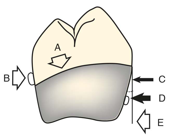
Retention
Retention is the property that allows the clasp assembly to resist displacement of the abutment tooth in the occlusal direction. Displacement forces can be activated by speaking, functional movements, chewing, sticky foods, or gravity. The clasp arm achieves retention by being positioned cervically to the height of contour on the tooth surface, and by the alloy’s resistance to distortion, preventing the clasp arm from detaching from this region. Therefore, the amount of flexibility corresponds to the distortion capacity at the moment force is applied to the tooth’s undercut. Another factor that has a lesser effect on retention is friction. The degree of frictional resistance depends on the type of interface between the tooth and the clasp assembly. Other factors include the amount of the encircled tooth surface, the precision of the clasp-tooth contact, the type of alloy used (cast alloys provide greater retention than wrought wire forms), and the approach direction of the retentive tip to the undercut area.
The most important factor in determining the degree of retention provided by the clasp is the flexibility of the clasp arm, along with the amount of horizontal undercut engaged by the retentive tip.
The degree of flexibility of the clasp arm depends on the following factors:
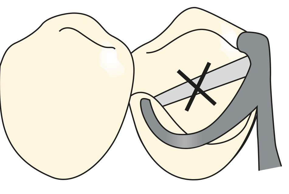
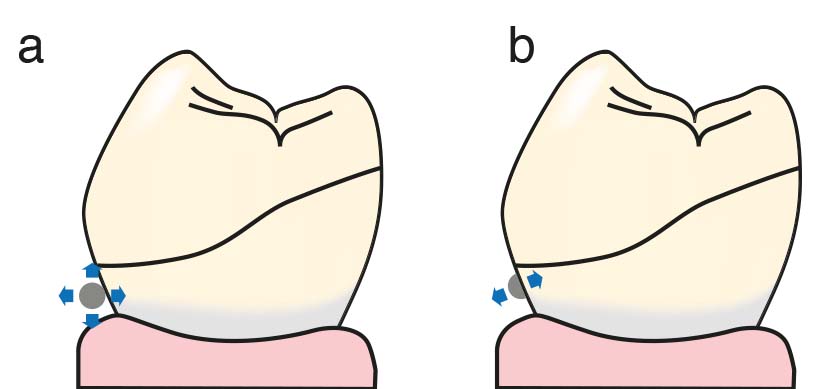
- Length of the clasp arm: As the length increases, the amount of flexibility also increases (Figure 3-3). The bar clasp arm is more flexible than the arms of a circumferential clasp (Figure 3-4).
- Diameter of the clasp arm: As the diameter decreases, the amount of flexibility increases (Figure 3-5).
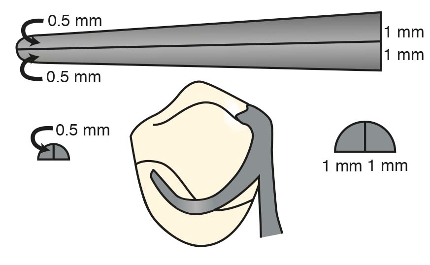
- Cross-sectional shape of the clasp arm: A clasp arm with a round cross-section has greater flexibility than one with a half-round cross-section (Figure 3-6).
- Tapering of the clasp arm toward the tip: Proper tapering of the clasp arm can increase its flexibility by up to four times. This feature allows the retentive tip to become thinner and significantly more flexible. The retentive arm should taper uniformly from its origin at the body to the terminal end. For a circumferential clasp, the diameter of the clasp arm at the tip should be approximately half of its diameter at the origin. The approaching arm of a bar clasp should be tapered in the same manner (Figure 3-7).
- Type of alloy: Cast Co-Cr alloy has a higher modulus of elasticity than a gold alloy of the same diameter and is therefore less flexible than gold.
- Form of alloy: A wrought wire alloy provides greater flexibility than a cast alloy of the same diameter.
Stabilization
Stabilization refers to the resistance of the clasp to displacement of the denture in the horizontal plane. All clasp components except the retentive tip contribute to this property to varying degrees. The circumferential clasp exhibits better stabilization than bar or combination clasps because it has two rigid shoulder segments, whereas the retentive elements of other clasps are more flexible.
Support
Support is the resistance of the clasp to gingival displacement. The occlusal (lingual or incisal) rest is the most critical component in providing support. However, the body and shoulder of the clasp also contribute to support to some extent, as they are positioned above the height of contour of the abutment tooth.
Encirclement
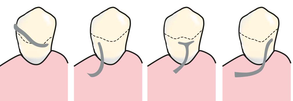
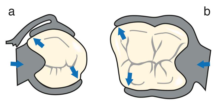
To prevent the clasp arms from moving away from the abutment tooth when forces are applied to the prosthesis, the clasp must encircle at least 180° of the crown of the abutment tooth (Figure 3-8).
Reciprocation
Reciprocation refers to “the counteraction of a force generated by one part of an appliance by another part.” When applied to removable partial denture clasps, reciprocation means that “the effect of the retentive clasp arm on the abutment tooth is neutralized by the non-retentive clasp arm on the opposite side.”
The primary function of the reciprocal arm is to counteract the horizontal forces generated as the retentive arm passes over the undercut area during insertion and removal of the prosthesis. Therefore, the position (horizontal or vertical) and shape of the reciprocal arm on the abutment tooth are of critical importance.
Horizontal Reciprocation
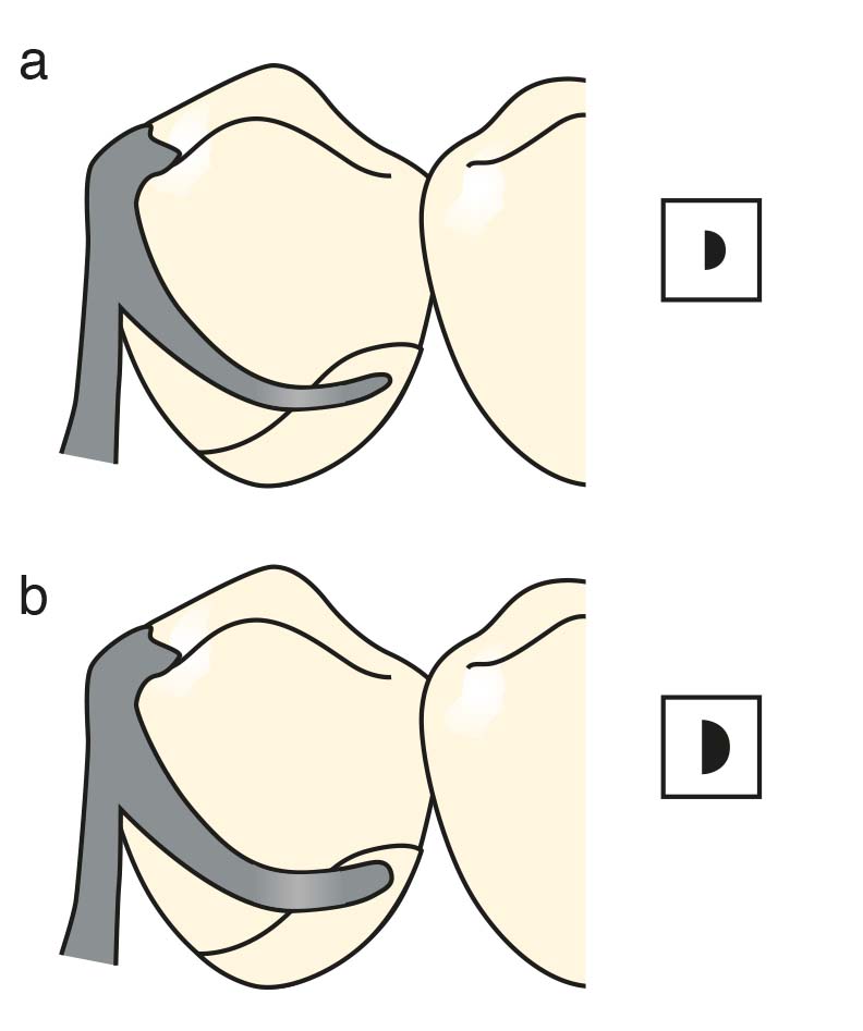
The horizontal reciprocal arm approach is the most commonly used but the least effective method. For the stabilization arm to function effectively, it must remain in continuous contact with the tooth surface, parallel to the path of insertion, on the opposite side of the retentive clasp. Typically, the stabilization arm is placed on a curved lingual surface at or just above the height of contour (Video 3-9).
a) When the retentive clasp arm does not contact the tooth before passing over the height of contour.
b) The reciprocal arm attempts to balance the force created by the retentive arm by engaging the tooth from the opposite surface.
Since this arm does not contact the tooth surface until all components of the clasp are in place, reciprocation cannot be achieved. For it to be effective, the opposing tooth surfaces where the reciprocal elements will function must be parallel to the path of insertion, and the reciprocal and retentive clasp arms must simultaneously contact their respective tooth surfaces during the insertion and removal of the prosthesis (Video 3-10).
The effect of a non-parallel reciprocal arm that does not move in coordination with the retentive clasp arm is limited when placed on the abutment tooth surface.
Vertical Reciprocation
The function of the vertical reciprocal component is to resist the forces created when the retentive clasp arm flexes above the height of contour of the abutment tooth during insertion and removal of the prosthesis. The vertical reciprocal component is a rigid minor connector designed to be parallel to the path of insertion (Figure 3-11).
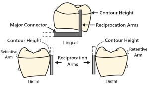
The key difference between the conventional horizontal stabilization arm and the vertical arm approach is that the tooth surfaces in contact with the horizontal stabilization arm must be parallel to the path of insertion. In contrast, with the vertical reciprocal arm approach, the tooth surfaces do not need to be prepared parallel in order to maintain contact between the stabilization arm and the tooth surface during insertion and removal of the prosthesis. The vertical stabilization arm is designed to maintain contact with a small mesiodistal portion of the lingual contour height of the abutment tooth during the insertion and removal of the prosthesis.
Passivity
The clasp must be passive when placed on the abutment tooth. This means that the clasp should not apply any pressure to the abutment tooth until it is activated during the functional movement of the prosthesis or when the prosthesis is removed from the mouth. During function, the inevitable small movements of the prosthetic base, due to the displacement of soft tissues, highlight the importance of passivity. A clasp designed in this way allows the base to move slightly without applying harmful stress to the abutment tooth (Figure 3-12).