Major connectors
Due to anatomical differences between the maxilla and mandible, the design and types of major connectors used in the upper and lower arches differ from one another.
Maxillary major connectors
On the tissue-surface of the maxillary major connector, a stop line is created along the peripheral border. This feature prevents the major connector from being embedded into the tissue and ensures proper adaptation between the connector and the underlying mucosa, thereby preventing food entrapment. The stop line is formed by preparing a groove 0.5 to 1.0 mm in depth and width on the master cast for the removable partial denture, and it should terminate 6 mm away from the gingival margins of the teeth. The depth of the stop line is determined according to the resiliency of the underlying tissues. It is prepared deeper along the lateral slopes of the hard palatal mucosa and shallower in the horizontal region overlying the median palatal suture.
Four basic types of maxillary major connectors are considered:
- Palatal strap
- Double palatal strap
- U-shaped palatal connector
- Full palatal plate
Palatal Strap
Although it is associated with the edentulous area, palatal strap typically presents as a uniform-width strap that does not cover the free gingival margins, with its anterior border often located at the level of the rugae and its posterior border at the junction of the hard palate. Since the anterior palatal region is left uncovered, it does not interfere with phonation and is considered the most comfortable type of major connector for the patient. It can be made narrower in cases with shorter edentulous ridges and wider in cases with longer ridges, but it must be at least 8 mm wide. To increase resistance to deformation, it should either have a narrow surface with increased thickness or a broad surface with decreased thickness. When broad contact is achieved with the hard palate, it can provide excellent palatal support. This is one of the most frequently used maxillary major connectors.
Indications:
- Class III modifications in which tooth-supported edentulous spaces are symmetrically located on both sides of the dental arch (Figure 5-1)
2. Certain Class I and Class II Mod. 1 cases that require the anterior palatal region to be left uncovered (Figure 5-2).
3. Class II and Class III cases in which, according to the concept of cross-arch stabilization, the support is provided from the tooth-supported side of the arch (Figure 5-3).
Contraindications:
- Presence of torus palatinus,
- Anatomical form of the hard palate being very rigid and flat,
- Inadequate distribution of edentulous areas.
Double palatal strap
Double palatal strap consists of two palate strap, one in the anterior and one in the posterior region. The anterior strap, shaped wide and flat according to the indentations and prominences of the rugae, does not interfere with phonation or cause discomfort to the tongue. The posterior strap is placed according to the condition of the edentulous space and is narrower and thicker compared to the anterior strap. Compared to the palatal strap, it has better resistance to deformation; however, it is less effective in terms of tissue support. The open areas outside the straps provide comfort for the patient. It is the most rigid among the maxillary major connectors; however, it may cause discomfort in patients with a gag reflex.
Indications:
- Modification Class II cases with a long span between the anterior and posterior abutment teeth (Figure 5-4) and Class III cases (Figure 5-5)
2. In the presence of a torus palatinus,
3. Patients who cannot tolerate a full palatal plate.
4. The palatal strap is extended anteriorly in Class IV cases to support the anterior edentulous region (Figure 5-6).
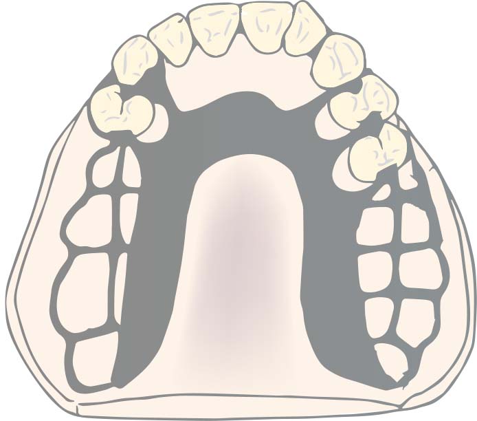
U-shaped palatal connector
U-shaped palatal connector (U-plate) covers the anterior palatal region and extends to the posterior lateral areas in a horseshoe shape (Figure 5-7).
To avoid discomfort to the patient, it should be at least 0.5 mm thick. The anterior palate’s anatomical reliefs are accurately replicated on the tissue-surface to reduce speech interruption.
Indications:
- Modified Class I cases requiring restoration of the anterior teeth,
- Cases requiring restoration of both anterior and posterior teeth,
- Presence of torus palatinus,
- When stabilization (splinting) of anterior teeth with weak periodontal support is required,
- In patients with a strong gag reflex and/or in cases where posterior palatal coverage cannot be tolerated.
Contraindications:
In distal extension cases, it is not recommended to use U-shaped major connector with a narrow midline area without extending to the anterior teeth, as this reduces its rigidity and prevents adequate force distribution (Figure 5-8).
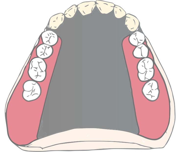
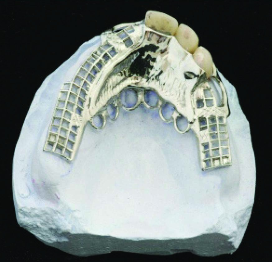
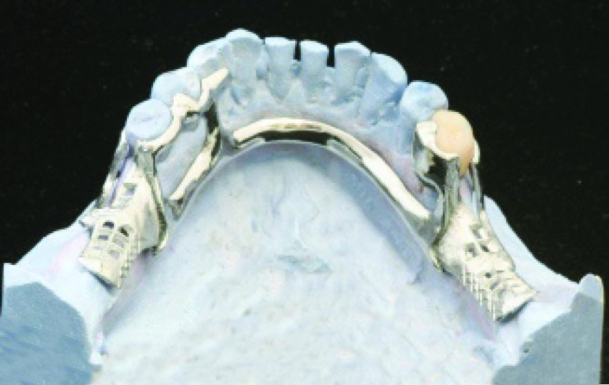
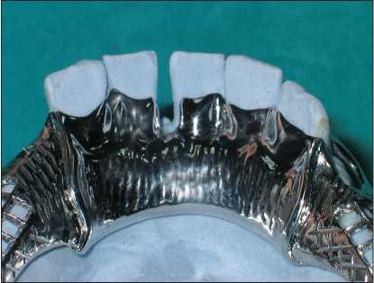
Full palatal plate
The full palatal plate is a major connector that covers the hard palate as widely as possible and provides maximum mucosal support. It distributes functional loads across a wide region, reducing the amount of load per unit area, thus offering physiological advantages. The movement of the distal extension denture base under functional forces decreases due to the increased retention and stability.
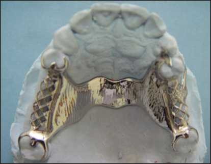
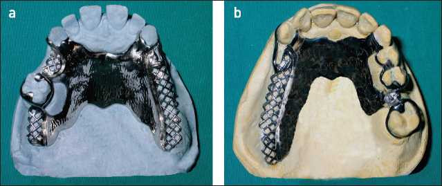
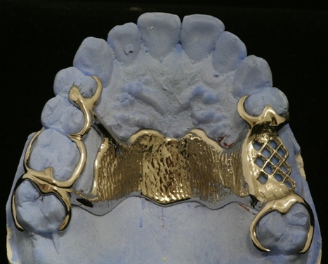
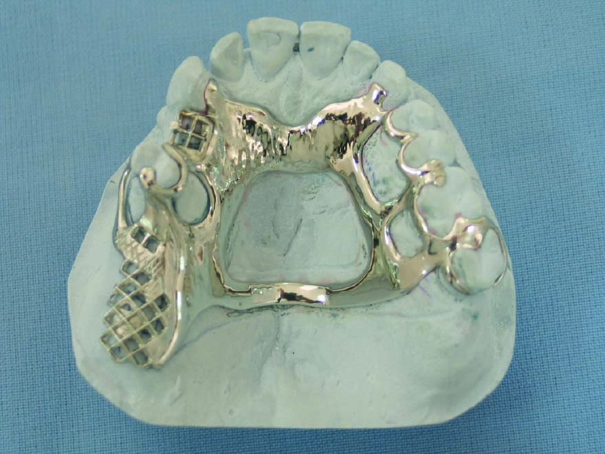
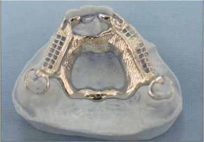
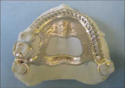
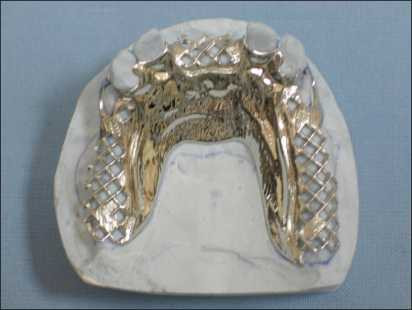
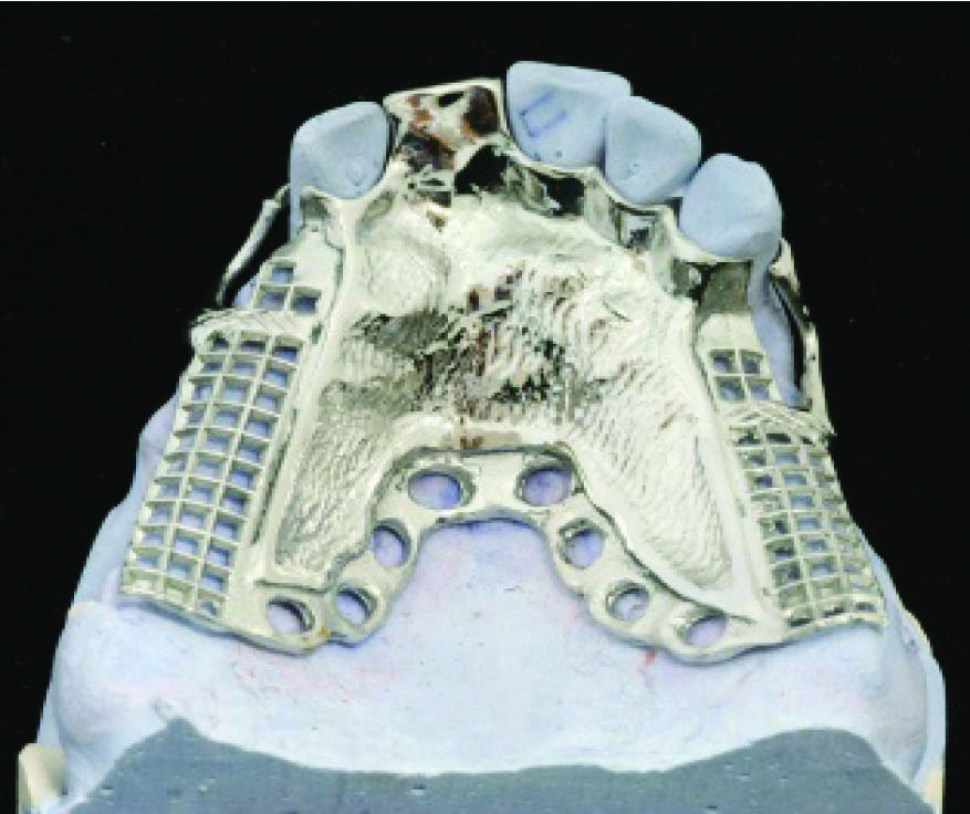
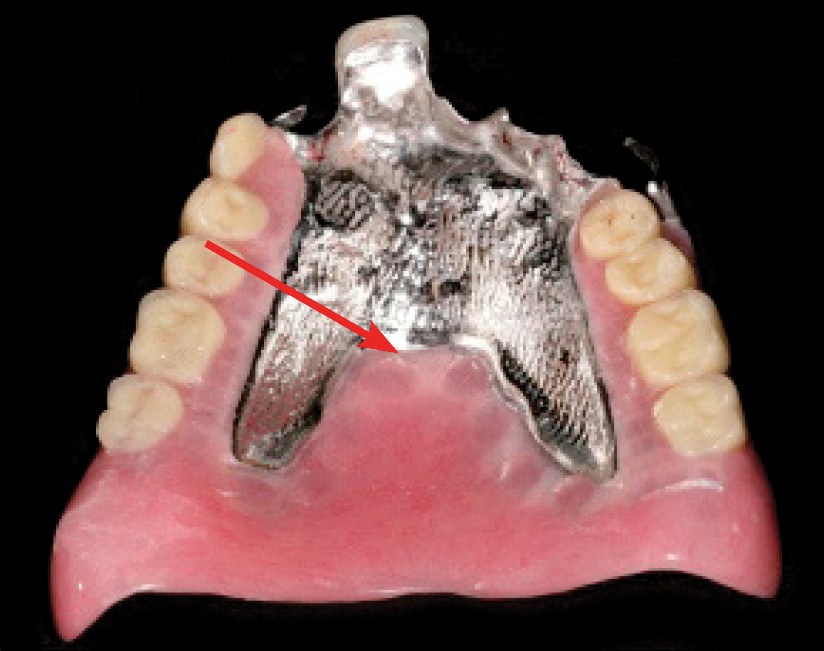
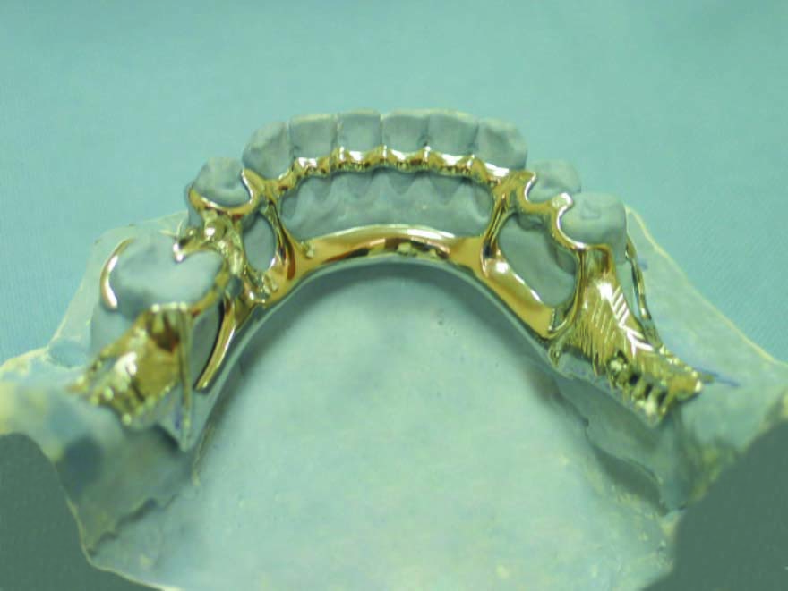
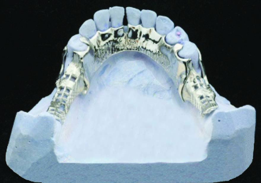
To replicate the natural anatomical structure of the hard palate on the tissue-surface of the plate, it should be thin; a thickness of 0.35 mm is sufficient. The prosthesis borders are shaped similarly to the complete denture base boundaries in the posterior region. The posterior borders can be completed with metal (Figure 5-9) or made from acrylic (Figure 5-10).
 |
 |
 |
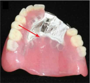 |
Acrylic resin palatal part of the major connector provides superior physical retention compared to metal denture borders. In such cases, a mesh framework that allows adequate retention of the acrylic must be provided (Figure 5-10 a and c).
Indications:
-
Cases where the majority of the periodontal support of the natural teeth has been lost,
-
When residual ridges have undergone extreme vertical resorption,
-
Cases where the anatomical form of the hard palate is flattened,
-
Treatment of patients with cleft palate using removable partial dentures.
Contraindication:
-
It should not be used in patients who cannot tolerate the greater tissue coverage compared to other major connectors.
Mandibular major connectors
Five basic types of maxillary major connectors are considered:
- Lingual bar
- Lingual bar with cingulum bar (continuous bar)
- Linguoplate
- Sublingual bar
- Labial bar
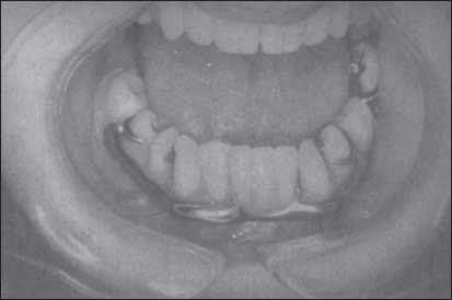
Lingual Bar
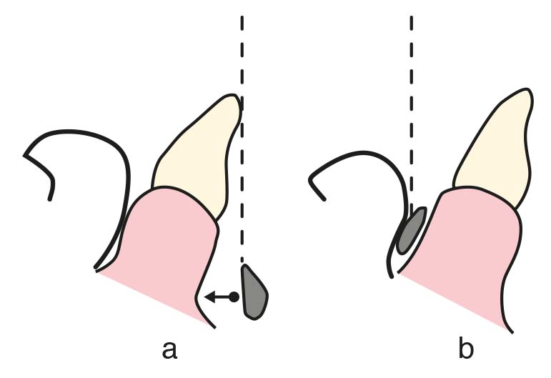
The basic form of a mandibular major connector is a lingual bar with a half-pear–shaped cross-section, with its thicker portion forming the inferior border (Figure 5-11). In order to ensure adequate rigidity, it should be at least 4 mm in both thickness and width. The superior border of the bar runs 2–3 mm away from the gingival margins of the mandibular anterior teeth. The inferior border should be positioned 1 mm above the floor of the lingual sulcus and must not interfere with the functional movements of the soft tissues in the floor of the mouth (Figure 5-12).
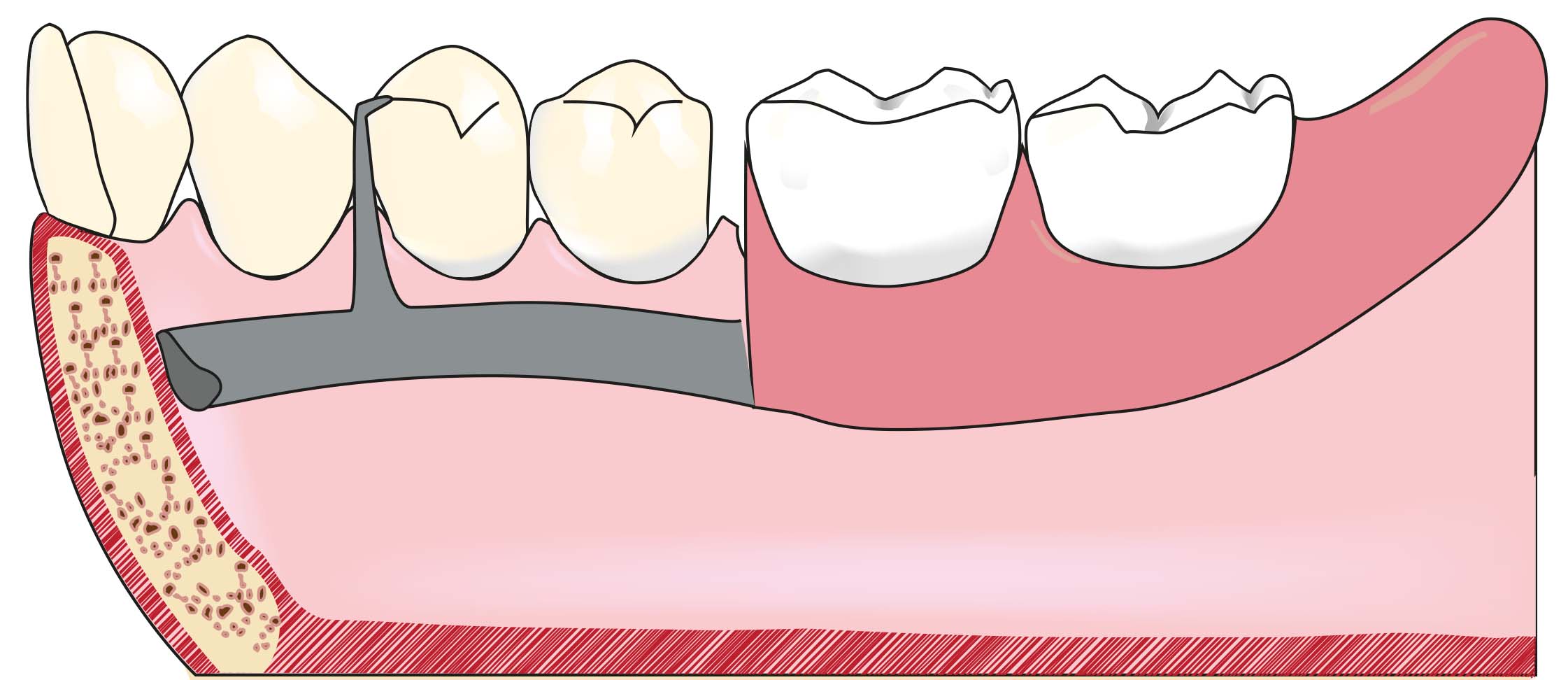
Therefore, a vertical space of 6–8 mm between the gingival margin and the floor of the mouth mucosa is required.
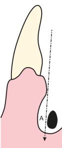
The lingual bar closely follows the lingual surface of the mandible; however, relief must be provided between the bar and the mucosa. The amount of relief depends on the inclination of the undercut between the soft tissue in the lingual region and the mandibular anterior teeth.
In distal extension removable partial dentures, greater relief is required compared to tooth-supported cases, as the denture base rotation around the primary fulcrum line under functional forces may cause trauma to the mucosa.
It is the simplest and most commonly used mandibular major connector and serves as the basis for other mandibular major connectors.
As it leaves the gingival margins exposed and does not contact supporting teeth or soft tissues, it minimizes food impaction and reduces the risk of caries and gingival inflammation due to dental plaque accumulation.
Indication:
- Due to its favorable characteristics, it is indicated in almost all mandibular cases.
Contraindications:
- Cases where the distance between the lingual sulcus and the gingival margin of the anterior teeth is less than 6 mm,
- Cases with a high lingual frenum,
- Cases with excessively inclined lingual tissues (Figure 5-13),
- Examples of cases where anterior teeth are missing,
- When indirect retention and/or stabilization (splinting) of anterior teeth is required with a major connector.
Lingual bar with cingulum bar
The cingulum bar, which runs along the lingual surfaces of the mandibular anterior teeth together with the lingual bar, forms the lingual bar with cingulum bar (Figure 5-14).
The cingulum bar runs along the lingual surfaces of the mandibular anterior teeth, functioning as a series of joined stabilizing clasp arms, and is supported at both ends by terminal rests. In addition to providing effective indirect retention, it contributes to the horizontal stability and support of the prosthesis. The two bars are connected at both ends by two minor connectors. The structure of the inferior bar is the same as that of the lingual bar.
The lingual bar with cingulum bar allows for the free flow of food and saliva through the interproximal spaces and permits physiological stimulation of the free gingiva by the tongue. When special right-angled rest seats are prepared in the cingulum area, force transmission occurs along the long axis of the teeth, resulting in improved outcomes.
Indications:
- In distal extension prostheses where indirect retention can only be achieved by the major connector,
- When the mesiodistal contact between the mandibular incisors is appropriate,
- In cases where the lingual tissues are not excessively inclined.
Contraindications:
- Presence of diastemata between the anterior teeth for various reasons (in such cases, the cingulum bar is placed below the lower boundary of the interproximal spaces to remain invisible, creating an interrupted cingulum bar),
- Short clinical crown length of the anterior teeth,
- Presence of a high lingual frenum.
Linguoplate
Linguoplate is a plate-shaped major connector that conforms to the lingual surface contours and interproximal embrasures of the mandibular anterior teeth. Except for the extensions that cover the interproximal areas and reach above the mesiodistal contact points, the linguoplate should not be placed higher than the middle thirds of the teeth (Figure 5-15).
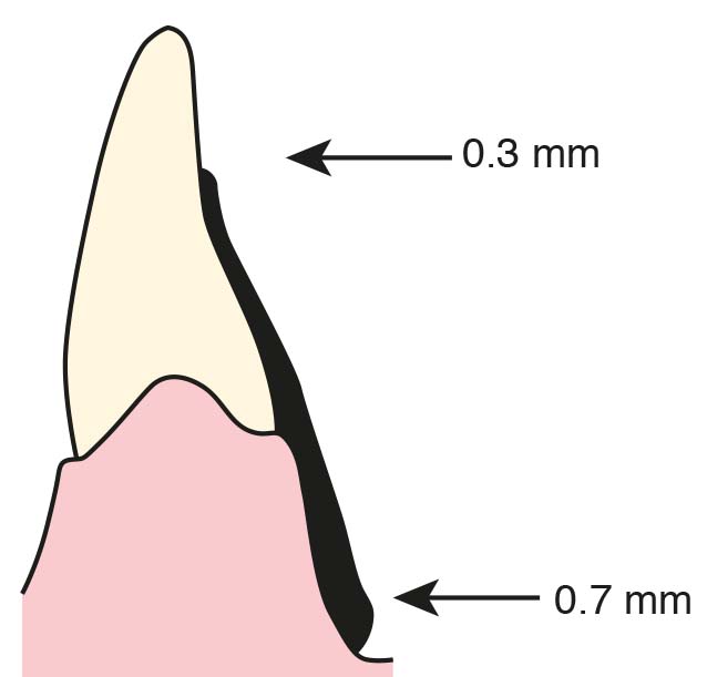
The superior boundary of the linguoplate should be the middle third of the lingual surfaces of the anterior teeth. The half-pear-shaped plate’s superior border, which is 0.3 mm thick at the superior border and 0.7 mm thick at the inferior border, is in harmony with the anatomical features of the anterior teeth (Figure 5-16).
To avoid food accumulation, the linguoplate should terminate above the height of contour of the posterior teeth if it extends to the posterior region. The lingual sulcus or, in the case of an undercut, the level of the lingual tissues’ contour marks the end of the plate’s lower border.
It is suggested that the gingival tissues in the lingual region being covered with plate and under pressure may impair gingival health because it prevents blood circulation, physiological stimulation of the tongue and saliva flow.
Indications:
- Examples of cases where anterior teeth are missing,
- Cases requiring the use of major connector for indirect retention,
- Cases in which surgical removal of the lingual torus is not possible,
- Excessively high lingual frenulum,
- Patients with excessive dental calculus accumulation (this issue is controversial as it prevents physiological stimulation),
- In order to splint anterior teeth with weak periodontal support due to its stabilizing feature,
- Presence of anterior teeth with an uncertain prognosis and expected to be lost in the near future (for the purpose of replacement of one or more incisor teeth to an existing linguoplate).
Contraindication:
Using linguoplate causes esthetic problems in the presence of lower anterior teeth with wide interproximal spaces (diastema). In this case, linguoplate is prepared in a way that shows an indented course towards the gingival margins of the teeth in diastema regions and is called interrupted linguoplate (Figure 5-17).
When viewed from the labial surface of the front teeth, the major connector metal is hidden by a unique design. Each tooth’s linguoplate extensions should have widths that are smaller than the mesiodistal diameters of the anterior teeth. To achieve enough rigidity, the plate’s thickness at the lower edge might be increased.
Sublingual Bar
The sublingual bar lies in the lingual sulcus. It is structurally similar to the lingual bar except that it is positioned lower (Figure 5-18).

Although it can be tolerated by patients with a round lingual sulcus, its use is discouraged because to the potential for tongue irritation, particularly of the lingual frenulum.
Labial Bar
The labial bar is located on the labial mucosa of the lower anterior group of teeth or in some cases extends to the buccal aspect of the posterior group of teeth (Figure 5-19).
Its cross-section is half pear-shaped, identical to the lingual bar. The labial bar must be higher and thicker than the lingual bar in order to have the same level of rigidity. The patient finds the thickness of the metal between the lip and the labial mucosa irritating since it is situated beyond the alveolar contour.
The labial bar has a very low possibility of becoming an effective treatment. Therefore, it is advised to minimize the need of labial bars by adopting particular techniques to remove the factors producing the path of insertion issue.
When premolars and anterior teeth are extremely lingually inclined, it is the only alternative (Figure 5-20).