
Systematic approach to surveying a diagnostic cast
The diagnostic cast is placed on the adjustable table of the dental surveyor and secured with its locking screw. The position of the table is adjusted so that the occlusal surfaces of the teeth are parallel to the platform of the surveyor, thereby determining the path of placement (Figure 7-10).
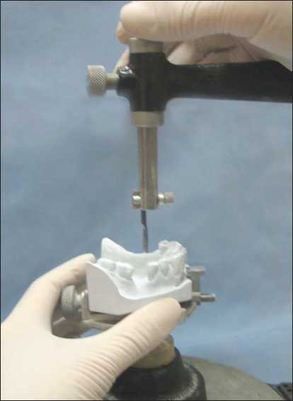
Although the terms “path of placement” and “cast tilt” are not synonymous, they are interrelated terms. Cast position refers to the orientation of the cast relative to the horizontal plane of the surveyor during the planning phase of the prosthesis. Therefore, the path of placement is parallel to the vertical arm of the dental surveyor.
In order to determine the path of placement, the guiding planes, retentive areas, interferences, and esthetics are first evaluated.
Identification of guide planes
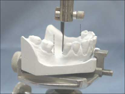
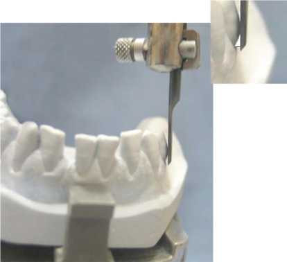
A surveyor blade is mounted to the dental surveyor to evaluate the existing or intended guiding plane surfaces (Figure 7-11a).
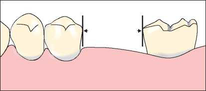
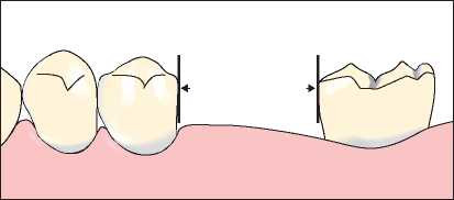
The surveyor blade is brought into contact with the proximal tooth surfaces of the abutment teeth, and the cast is tilted anteroposteriorly until all of these surfaces are parallel to each other (Figure 7-12).
When parallelism cannot be achieved in this manner, preparation is performed on the proximal tooth surfaces of any abutment tooth (Figure 7-11b). This procedure determines the anteroposterior cast tilt relative to the vertical arm of the dental surveyor.
Although the table of the dental surveyor can be adjusted in all directions, it should be understood that it permits movement primarily along two axes: anteroposterior and lateral tilting.
Guiding planes are generally prepared on enamel surfaces. When crown restorations are required on teeth designated for guiding plane preparation, wax patterns are shaped using the surveyor’s wax trimmer to ensure the guiding plane surfaces are parallel to the path of placement.
Surfaces other than the proximal areas of abutment teeth can also serve as guiding planes. When it is desired for the stabilization arm of the clasp assembly to contact the axial surface of the abutment tooth in harmony with the path of placement, lateral tilting of the cast may be required in addition to anteroposterior tilt.
The borders of proximal tooth surfaces requiring preparation are marked using a red pencil.
Identification of retentive areas
The surveyor blade is brought into contact with the buccal and lingual surfaces of the abutment teeth suitable for clasping to determine the amount of retentive area located below the survey lines. When the side surface of the blade attached to the surveyor is positioned to contact the abutment tooth surface and a light source is directed from behind, a triangular shape becomes visible. This triangle is bounded on one side by the abutment tooth surface and on the other side by the surveyor blade (Figure 7-13).
The cast is tilted laterally until a similar amount of undercut area is obtained on the terminal abutment teeth on both sides of the dental arch; however, to avoid disturbing the previously established anteroposterior tilt, the table is rotated around an imaginary anteroposterior axis. In the resulting position, the guiding planes should be parallel to each other, and the amount of retentive areas on the abutment teeth should be balanced.
When teeth lacking sufficient undercuts must be used as abutments, appropriate contouring through tooth surface reduction or crown restoration may be necessary. Wax patterns for cast restorations intended for abutment teeth are also evaluated on the dental surveyor, ensuring that the reciprocal arms of the clasps are positioned below the occlusal surfaces while the retentive arms are located in the cervical one-third of the crown, providing the most advantageous esthetics.
Although tilting the cast is advantageous for creating undercuts, it is a deceptive procedure because it only minimally affects the amount of retention. When no undercut exists on a tooth surface relative to one horizontal plane, tilting the cast relative to another horizontal plane will not effectively increase the prosthesis’s resistance against dislodging forces. For an undercut to truly be retentive, it must be clearly visible in all possible paths of placement.
Identification of interference areas
A carbon marker is mounted on the dental surveyor to identify interference areas, and potential solutions are considered. Changing the path of placement to eliminate interference may result in losing the previously established cast position for the guiding planes and retentive areas. In such cases, a decision must be made between removing the interference or re-evaluating the guiding planes and retentive areas.
After determining the final path of placement, areas requiring intraoral preparation due to interference are marked with a red pencil.
Esthetic Evaluation
In the established path of placement, the positions of the retentive clasps and the arrangement of the artificial teeth are also evaluated in terms of esthetics. To minimize the visibility of clasps in the anterior region, it is recommended to tilt the cast so that the survey lines are brought closer to the gingival margin without compromising periodontal health.
When the surfaces of abutment teeth adjacent to edentulous spaces are bell-shaped and often tipped or rotated, the amount of preparation required to correct these surfaces related to the path of placement can be determined using the dental surveyor. Another option for reducing undercut areas is to slightly tilt the cast in a posterior direction, which helps minimize the amount of tooth reduction required on abutment teeth for mouth preparation.
The final path of placement of the prosthesis corresponds to the final cast tilt in the anteroposterior and lateral directions, which is recorded in alignment with the vertical arm of the surveyor and best accommodates the four main factors: guiding planes, retentive areas, interferences, and esthetics.
All necessary mouth preparations must be marked in red pencil on the diagnostic cast. These markings indicate both the amount of correction needed and the plane on which the preparation should be carried out. Using the surveyor blade that represents the path of placement, the red-marked areas on the cast can be scraped. The surfaces obtained through scraping represent the amount of intraoral preparation required and the angle at which the rotary instrument should be applied.
After performing the necessary corrections on the diagnostic cast, a preliminary prosthesis design is drawn on the diagnostic cast using a pencil.
This treatment planning phase, which involves graphically recording the treatment plan before any mouth preparation, also includes the localization of rest seat positions.
The final cast position is recorded on the dental surveyor using the tripod or notch method.