
Biomechanical principles
Three different biomechanical principles need to be thoroughly understood in order to comprehend the forces that RPDs represent to the oral tissues when masticatory forces are applied. These principles are: (1) the inclined plane, (2) the lever, and (3) the snowshoe principle.
Inclined plane principle
When two objects come together on an inclined plane, they share a contact surface that forms a narrow angle with the horizontal plane. The application of a vertical force causes the two objects to move in opposite directions (Figure 1-14).
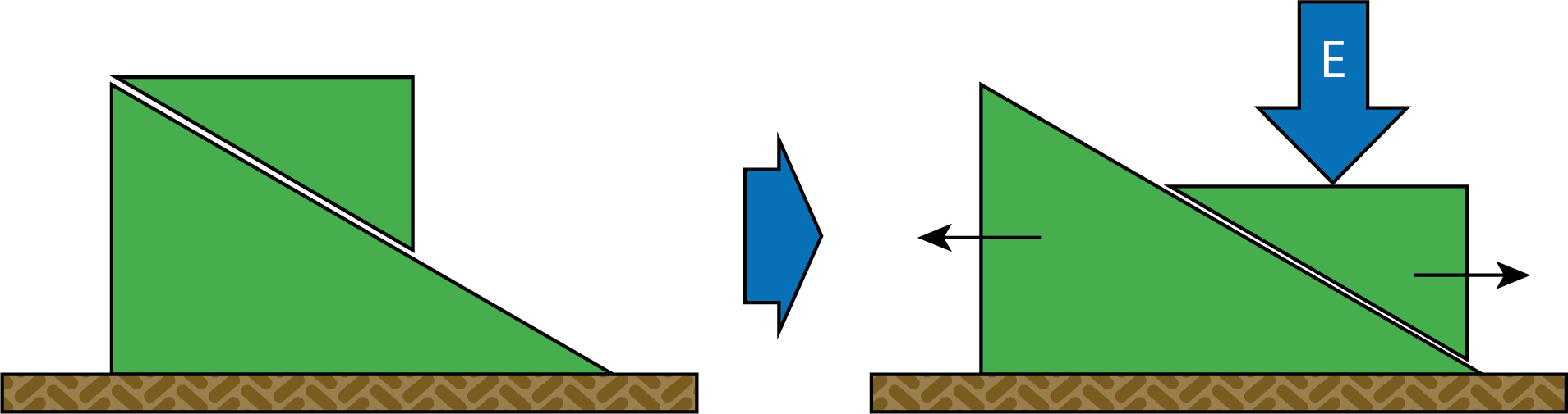
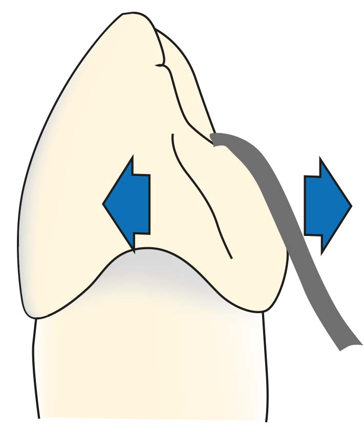
Prosthetic components are not placed on inclined surfaces of abutment teeth, as they can generate harmful forces (Figure 1-15).
Lever principle
A rigid bar supported at any point along its length is a lever. The point of support is called the fulcrum, and the lever can rotate around the fulcrum.
The function of a lever depends on the positioning of the fulcrum, the object, and the force; there are three classes of levers. The first class lever is most effective in lifting a load and providing leverage, while the second class lever is less effective, and the third class lever is the least effective system.
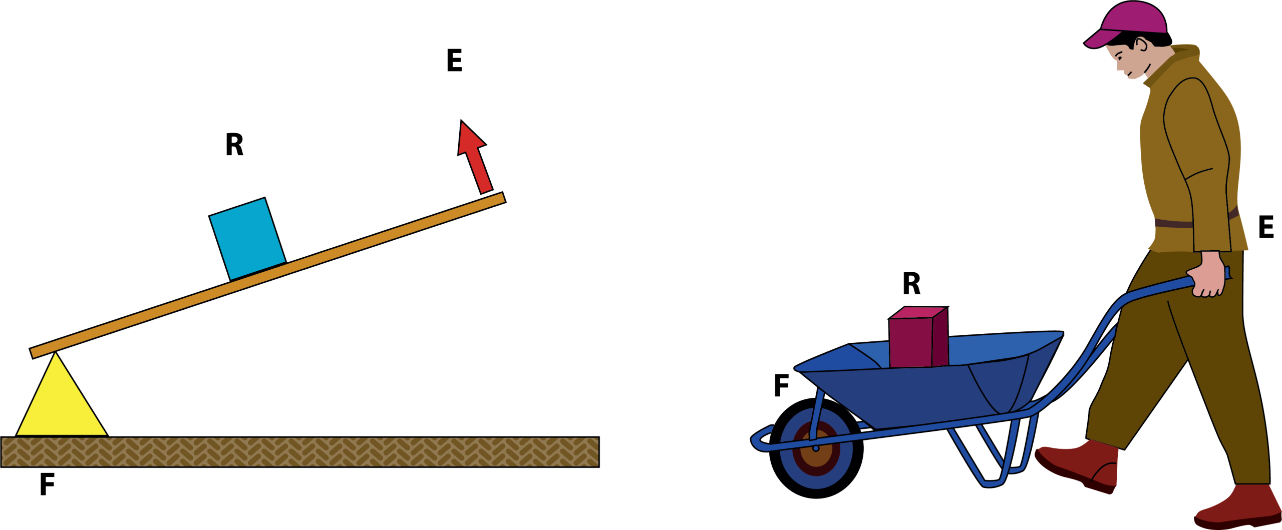
When we consider the issue of leverage in terms of RPDs, the most harmful forces arise in the first class lever system (Figure 1-16).

In the first class lever, the fulcrum (F) is in the middle, and the force (E) and resistance = load (R) are at both ends. It involves a typical seesaw motion and is the most efficient type of lever.
In removable partial dentures, the rotation of the prosthesis around the primary fulcrum axis, both towards and away from the tissue, results from the first class lever system (Figure 1-17a and Figure 1-17b).
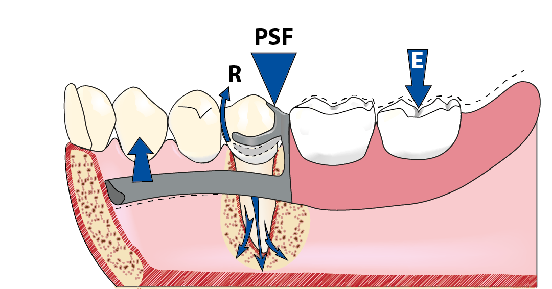
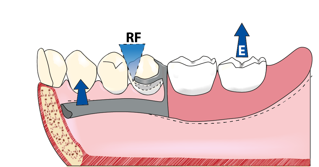
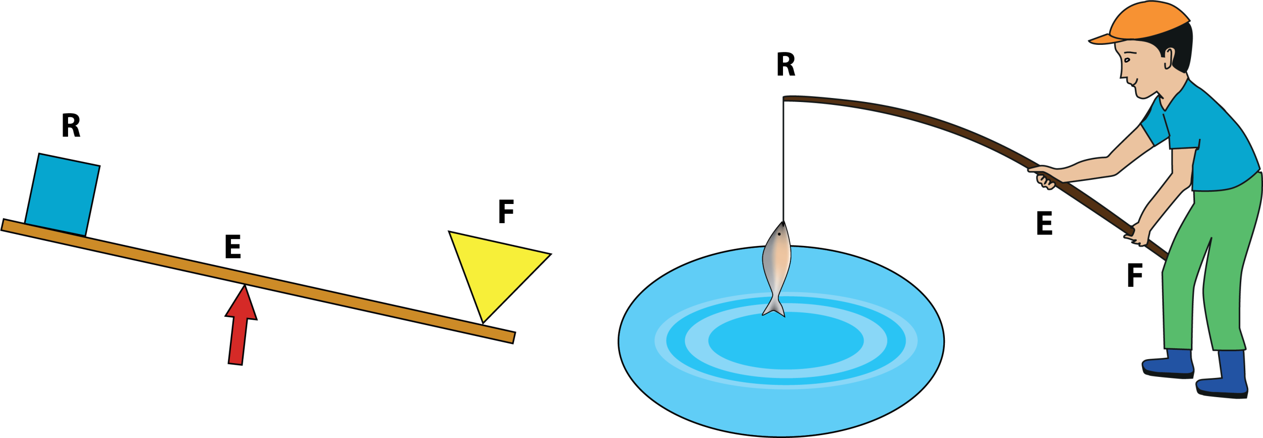
A distal-extension denture with a disto-occlusal rest and a cast circumferential direct retainer displays the first class lever system. The disto-occlusal clasp forms the fulcrum in the center. When force is applied to the distal end of the free-end saddle, the clasp tip at the undercut area attempts to move towards the survey line via a lever movement, forcing the abutment tooth into a distal tipping motion. In the second class lever, the fulcrum (F) is at one end, the force (E) is at the other end, and the resistance = load (R) is in the middle. This produces a typical wheelbarrow motion. It is less effective (Figure 1-18).
A distal-extension denture with a mesio-occlusal rest and a cast circumferential direct retainer (or bar clasp) displays the second class lever system. Since the lever’s effectiveness is lower, the prosthesis base movements are less significant compared to the first class. Furthermore, when the prosthesis base moves away from the tissue due to gravity or sticky foods, the clasp tip falls deeper into the undercut area, and no harmful effect occur on the abutment tooth (Video 1-19).
In the third class lever, the fulcrum = support (F) and resistance = load (R) are at both ends, while the force = (E) is in the middle. It is the least effective lever system, functioning like a fishing rod (Figure 1-20).
In tooth-supported RPDs, the third class lever effect is observed. However, since the movements of the denture base cause minimal non-axial forces on the abutment teeth, they are not of major concern (Video 1-21).
Mechanical advantage
The ability of a lever system to increase force is known as mechanical advantage. The force arm to resistance arm ratio is known as mechanical advantage (MA). The resistance arm refers to the distance between the point of resistance and the fulcrum, whereas the force arm denotes the distance from the point at which force is applied to the fulcrum. A mechanical advantage is achieved when the force arm is longer than the resistance arm (Figure 1-22).

When the mechanical advantage increases (MA > 1), the movement of the lever also increases. In a free-end removable partial denture, the mechanical advantage is greater than one. However, a high mechanical advantage leads to increased denture base movement, which is undesirable as it may cause damage to the supporting tissues.
The snowshoe principle
Wearing wide-soled snowshoes is essential for walking on snow without sinking. The base cannot sink into the supporting tissues because the chewing forces are dispersed across a large surface, lowering the force per unit area. This idea dictates that, within physiological bounds, distal-extension denture bases should cover the greatest amount of edentulous tissue.