Maxillary Kennedy Cl I
Maxillary Kennedy Cl I
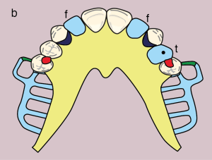
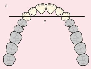
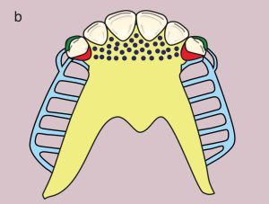
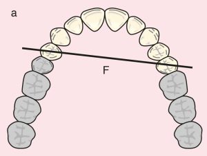
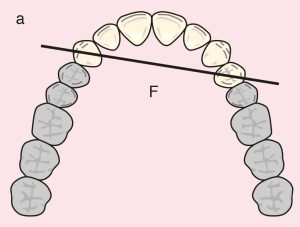
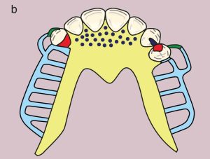
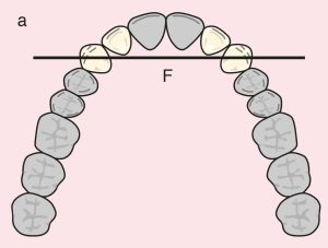
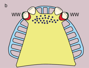
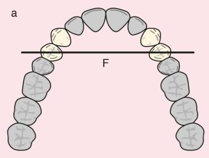
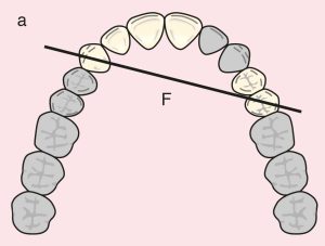
Case 1: Figure 11.1
Case description and design parameters
Case classification:
Two distal extension edentulous spaces, Class I
Support areas:
Tooth support: Terminal abutments; diametric fulcrum axis between teeth 15 and 25
Occlusal rest: Teeth 15 and 25 (mesio-occlusal)
*In case of interocclusal interference: teeth 15 and 25 (disto-occlusal)
Tissue support: Mucosal support in the distal extension edentulous area
Guide plane:
Distal extension; teeth 15 and 25
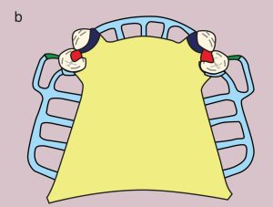
Direct retainer:
Bar clasp; teeth 15 and 25 (I-bar; mesio-buccal undercut, Modified T-bar; disto-buccal undercut)
*In the presence of a soft tissue undercut, gingival clasp; teeth 15 and 25 (mesio-buccal undercut)
Reciprocation: Stabilizing arm and proximal plate
Indirect retainer:
Auxiliary occlusal rest; teeth 14 and 24 (mesio-occlusal)
*Adding a canine extension to the auxiliary occlusal rest increases its effectiveness.
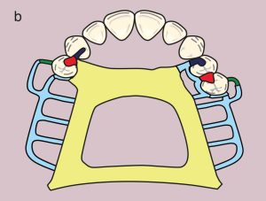
Major connector:
Double palatal bar
*In the presence of a torus or gag reflex, a U-plate covering the rugae for an alternative rigid major connector
Minor connectors:
Approaching arms of bar clasps, minor connectors that link the occlusal rests, indirect retainers, and artificial teeth to the major connector.
Denture base and artificial teeth:
Distal extension bases; metal-acrylic bases with acrylic artificial teeth
Case 2: Figure 11.
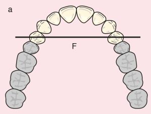

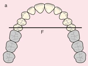
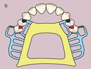
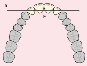
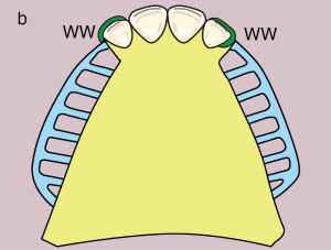
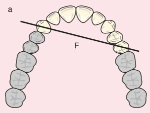
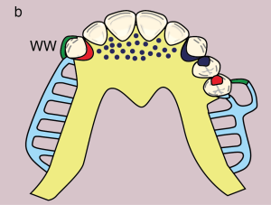
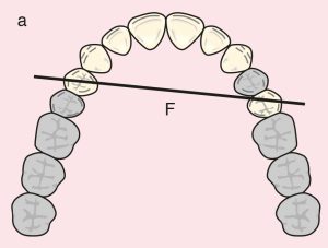
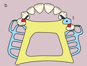
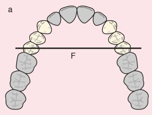
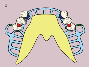
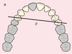
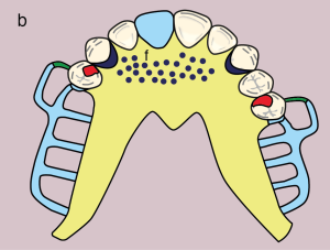
Case 3: Figure 11.3
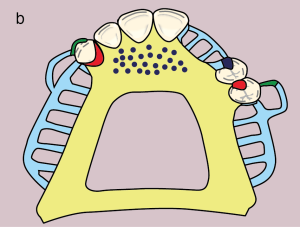
Figure 11.3. a) Cl I: The diametric fulcrum axis passing through the terminal abutments 13 and 23.
b) Metal framework design (Dotted area on the U-plate: Ruga support; indirect retention)
Case 4: Figure 11.4
Case 5: Figure 11.5
Case 6: Figure 11.6
Case 7: Figure 11.7
Maxillary Kennedy Cl I modifications
Case 8. Figure 11.8
Case description and design parameters
Case classification:
Two distal extension and one tooth supported edentulous areas; Cl I Mod 1
Support areas:
Tooth support: Terminal abutments; diagonal fulcrum axis between teeth 14 and 25
Occlusal rests: 14 and 25 (MO)
Secondary support: Cingulum rest on 23
Tissue support: Mucosal support on the distal extension areas
Guide plane:
Distal extension: 14 and 25 (D), tooth-supported: 23 (D), 25 (M)
Direct retainer:
Bar clasp: 14 and 25 (I Bar; MB undercut, Modified T Bar; DB undercut)
Reciprocation: MO rests along with proximal and palatal plates
*In the presence of soft tissue undercut, gingival clasp: 14 and 25 (MB undercut)
Indirect retainer:
Canine extensions on 13 and 23
Major connector:
Double palatal bar
*In case of gag reflex, U-plate covering the rugae for an alternative rigid major connector
Minor connectors:
Those connecting the approaching arms of bar clasps and artificial teeth to the major connector
Denture base and artificial teeth:
Distal extension bases; metal-acrylic base, acrylic artificial teeth and tube tooth on 24
Case 9. Figure 11.9


Case 10. Figure 11.10
Case 11. Figure 11.11
Case 12. Figure 11.12
Case 13. Figure 11.13
Case 14. Figure 11.14
Case 15. Figure 11.15