Maxillary Kennedy Cl III

Maxillary Kennedy Cl III

Case 26. Figure 11.26

Figure 11.26. a) Class III: Quadrilateral support plane formed by the terminal abutments of teeth 24, 28, 14, and 17.
Figure 11.26. b) Metal framework design.

Case description and design parameters

Case classification:
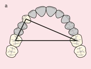
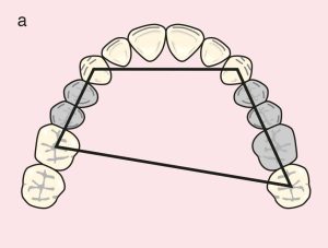
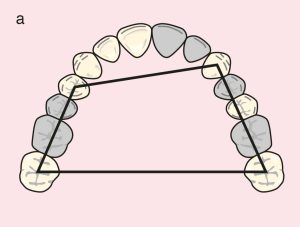
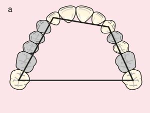
A single tooth-supported edentulous area; Class III

Support areas:
Tooth support: Terminal abutments; quadrilateral support plane formed by the terminal abutments of teeth 24, 28, 14, and 17
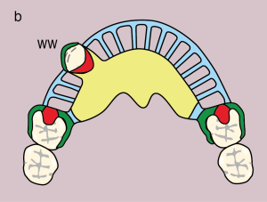
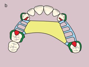
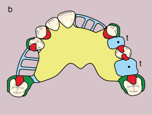
Occlusal rests: 14 and 24 (DO), 17 and 28 (MO)

Guide planes:
Tooth-supported: 24 (D), 28 (M)
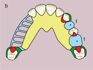
Direct retainer:
Akers clasps; 14 and 24 (MB undercut), 17 and 28 (DB undercut)

If interocclusal space is insufficient, the clasp on tooth 14 may be omitted; in this case, only the occlusal rest (DO or MO) is used to support the major connector.

Reciprocation:
Reciprocating clasp arm

Indirect retainer:
Not required due to the absence of a distal extension base

Major connector:
Palatal strap

Minor connectors:
Elements connecting the clasps and artificial teeth to the major connector

Denture base and artificial teeth:
Tooth-supported base; metal-acrylic base and acrylic artificial teeth

Maxillary Kennedy Cl III modifications


Case 27.
Figure 11.27

Figure 11.27. a) Class III Mod 1: Quadrilateral support plane formed by the terminal abutments of teeth 23, 27, 13, and 16.
Figure 11.27. b) Metal framework design.
Figure 11.27. b) Metal framework design

Case 28. Figure 11.28

Figure 11.28. a) Cl III Mod 2: Quadrilateral support plane formed by the terminal abutments of teeth 23, 27, 14, and 17.
Figure 11.28. b) Metal framework design.

Case classification:
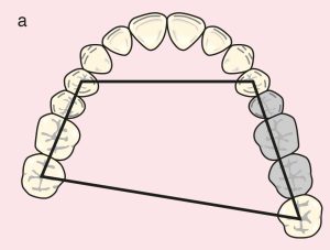
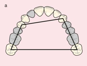
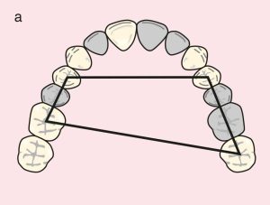
Three tooth-supported edentulous areas; Class III Mod 2

Support areas:
Tooth support: Quadrilateral support plane formed by the terminal abutments of teeth 23, 27, 14, and 17
Secondary abutments: 11, 13, and 14
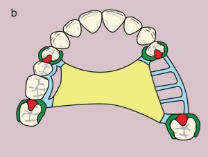
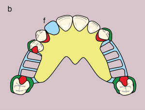
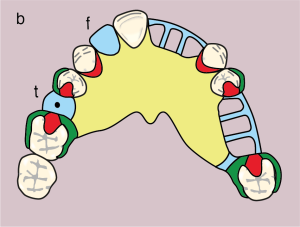
Occlusal rests: 17 and 27 (MO), 14 (DO)
Cingulum rests: 13, 11, and 23

Guide planes:
Tooth-supported: 11, 14, 23 (D) and 13, 17, 27 (M)

Direct retainer:
Akers clasps: 14 (MB undercut), 17 and 27 (DB undercut); gingival clasp: 23 (MB undercut)

Reciprocation:
Proximal plate and cingulum rest: 23; reciprocating clasp arms: 14, 17, and 27

Indirect retainer:
Not required due to the absence of a distal extension base

Major connector:
U-shaped plate

Minor connectors:
Elements connecting the clasps and artificial teeth to the major connector

Denture base and artificial teeth:
Tooth-supported base; metal-acrylic base with acrylic artificial teeth and facing tooth

Case 29. Figure 11.29


Figure 11.29. a) Cl III Mod 3: Quadrilateral support plane formed by the terminal abutments of teeth 23, 27, 14, and 17.
Figure 11.29. b) Metal framework design.

Case 30. Figure 11.30

Figure 11.30. a) Cl III Mod 3: Quadrilateral support plane formed by the terminal abutments of teeth 24, 27, 14, and 16.
Figure 11.30. b) Metal framework design.


Case 31. Figure 11.31

Figure 11.31. a) Cl III Mod 2: Quadrilateral support plane formed by the terminal abutments of teeth 23, 27, 12, and 17.
Figure 11.31. b) Metal framework design.


Case 32. Figure 11.32

Figure 11.32. a) Cl III Mod 1: Triangular support plane formed by the terminal abutments of teeth 13, 16, and 26.
Figure 11.32. b) Metal framework design.


License

A Guide to Removable Partial Denture Planning Copyright © 2025 by Funda Akaltan. All Rights Reserved.

Share This Book