Maxillary Kenndey Cl lV

Maxillary Kenndey Cl lV

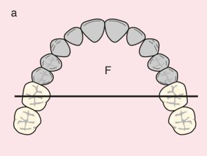
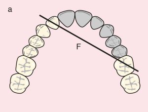
Case 33. Figure 11.33

Şekil 11.33. a) Cl IV: Diametric fulcrum line passing through the terminal abutments of teeth 14 and 24.
Şekil 11.33. b) Metal framework design.

Case description and design parameters

Case classification:
A single anterior edentulous area; Class IV

Support areas:
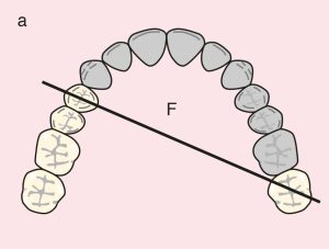
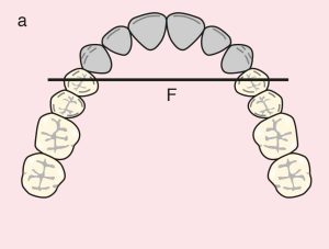
Tooth support: Diametric fulcrum line passing between the terminal abutments of teeth 14 and 24
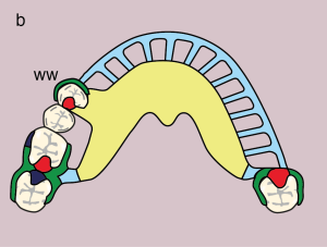
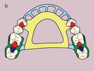
Occlusal rests: 14 and 24 (DO)
Embrasure rests: 16, 17 and 26, 27
Tissue support: Mucosal support in the anterior edentulous area

Guide planes:
Anterior edentulous area: 14 and 24 (M)
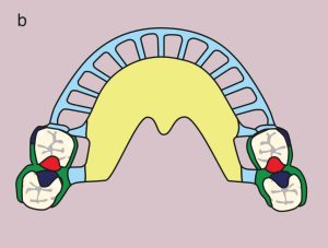
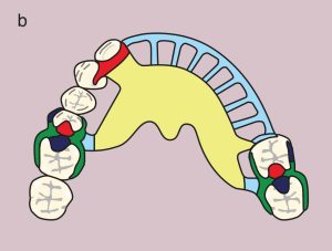
Direct retainer:
Double Akers clasps; 16 (MB undercut), 17 (DB undercut), 26 (MB undercut), 27 (DB undercut)
Reciprocation: Reciprocating clasp arms

Indirect retainer:
Occlusal rests: 17 and 27 (MO)
Akers clasps: 16 and 26 (MB undercut)

Major connector:
Double palatal bar

Minor connectors:
Elements connecting the Akers clasps and artificial teeth to the major connector

Denture base and artificial teeth:
Anterior base; metal-acrylic base and acrylic artificial teeth


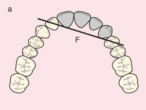
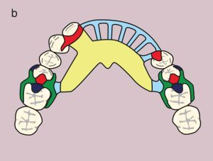
Case 34. Figure 11.33

Figure 11.34. a) Cl IV: Diametric fulcrum line passing through the terminal abutments of teeth 16 and 26.
Figure 11.34. b) Metal framework design.

Case 35. Figure 11.35

Figure 11.35. a) Cl IV: Diagonal fulcrum line passing through the terminal abutments of teeth 12 and 24.
Figure 11.35. b) Metal framework design.


Case 36. Figure 11.36

Figure 11.36. a) Cl IV: Diagonal fulcrum line passing through the terminal abutments of teeth 12 and 26.
Figure 11.36. b) Metal framework design.


Case 37. Figure 11.37

Figure 11.37. a) Cl IV: Diagonal fulcrum line passing through the terminal abutments of teeth 14 and 27.
Figure 11.37. b) Metal framework design.

License

A Guide to Removable Partial Denture Planning Copyright © 2025 by Funda Akaltan. All Rights Reserved.

Share This Book