Mandibular Kennedy Cl II
Mandibular Kennedy Cl II
Case 42. Figure 11.42
Case description and design parameters
Case classification:
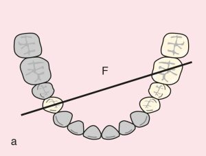
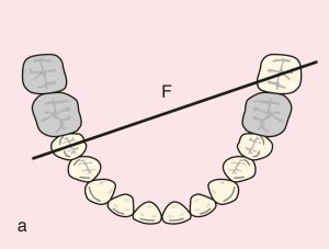
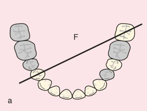
One distal extension edentulous area; Class II
Support areas:
Tooth support: Terminal abutments; diagonal fulcrum line passing between teeth 45 and 36
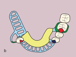
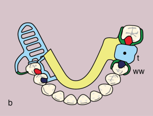
Embrasure rests: 45, 44 and 35, 36
Tissue support: Mucosal support in the distal extension edentulous area
Guide plane:
Distal extension: 45 (D)
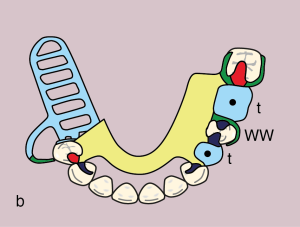
Direct retainer:
Bar clasp: 45 (I bar; MB undercut, Modified T bar; DB undercut) and Akers clasp: 36 (DB undercut)
Reciprocation: 45; occlusal rest with proximal plate, 36; reciprocal clasp arm
Indirect retainer:
Auxiliary occlusal rest and canine extension; 34 and 33
Major connector:
Lingual bar
Minor connectors:
Elements connecting the approach arm of the bar clasp, occlusal rest, indirect retainer, and artificial teeth to the major connector
Denture base and artificial teeth:
Distal extension base; metal-acrylic base and acrylic artificial teeth
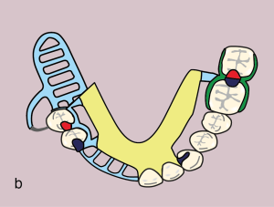
Mandibular Kennedy Cl II modifications
Case 43. Figure 11.43
Case description and design parameters
Case classification:
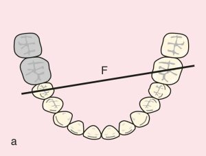
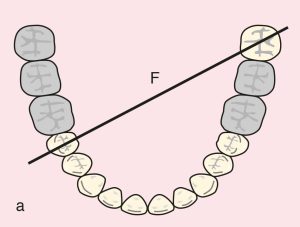
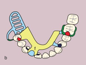
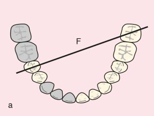
One distal extension and one tooth-supported edentulous area; Class II Mod 1
Support areas:
Tooth support: Terminal abutments; diagonal fulcrum line passing between teeth 45 and 37
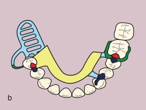
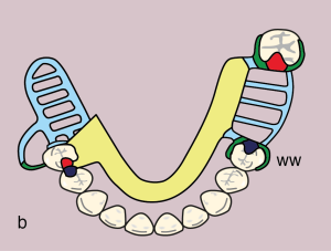
Occlusal rests: 35 (DO), 37, 44, 45 (MO)
Secondary support: 35; occlusal rest (DO)
Tissue support: Mucosal support in the distal extension edentulous area
Guide planes:
Distal extension: 45 (D)
Tooth-supported: 35 (D) and 37 (M)
Direct retainers:
Bar clasp: 45 (I bar; MB undercut, Modified T bar; DB undercut), Akers clasp: 37 (DB undercut), and wrought wire clasp: 35 (MB undercut)
Reciprocation: 45; stabilizing arm, 35 and 37; reciprocal clasp arm
Indirect retainers:
Occlusal rests: 35 (DO), 44 (MO)
Major connector:
Lingual bar
Minor connectors:
Elements connecting the approach arm of the bar clasp, embrasure rest, and artificial teeth to the major connector
Denture base and artificial teeth:
Distal extension base; metal-acrylic base, acrylic artificial teeth, and tube tooth; 36
Case 44. Figure 11.44
Case 45. Figure 11.45
Case 46. Figure 11.46

Case 47. Figure 11.47
Case 48. Figure 11.48