Mandibular Kennedy Cl III
Mandibular Kennedy Cl III
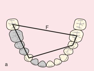
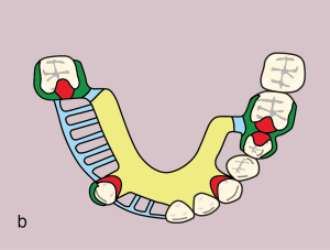
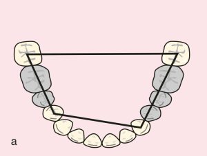
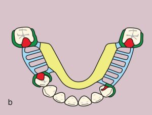
Case 49. Figure 11.49
Case description and design parameters
Case classification: One tooth-supported edentulous space; Cl III
Support areas:
-
Tooth support: Terminal abutments; quadrangular support plane between teeth 44, 48, 36, and 37
-
Occlusal rest: 44 (DO), 48 (MO), and 34 (M; to support the major connector and prevent deformation of the long lingual bar)
-
Embrasure rest: 36 and 37
Guide plane:
Tooth-supported; 44 (D), 47 (M)
Direct retainer:
Akers clasp; 44 (MB undercut), 47 (DB undercut)
Double Akers clasp; 36 (MB undercut) and 37 (DB undercut)
Reciprocation: Reciprocal clasp arm
Indirect retainer:
Not required due to absence of free-end saddle.
Major connector:
Lingual bar
Minor connectors:
Connecting the clasps and artificial teeth to the major connector
Denture base and artificial teeth:
Tooth-supported base; metal-acrylic base and acrylic artificial teeth
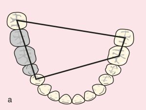
Mandibular Kennedy Cl III modifications
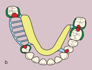
Case 50. Figure 11.50
Case description and design parameters
Case classification: Two tooth-supported edentulous spaces; Cl III Mod 1
Support areas:
Tooth support: Quadrangular sustentation plane between terminal abutments 33, 37, 44, and 47
Occlusal rest: 44 (DO), 47, 37 (MO)
Singulum rest: 33
Guide planes:
Tooth-supported: 33 (D), 37 (M), 44 (D), 47 (M)
Direct retainers:
Akers clasp: 44 (MB undercut), 47 (DB undercut), 37 (DB undercut), and 33 (MB undercut)
Reciprocation: Reciprocal clasp arm
Indirect retainers:
Not needed due to absence of free-end saddle.
Major connector:
Lingual bar
Minor connectors:
Connecting the clasps and artificial teeth to the major connector
Denture base and artificial teeth:
Tooth-supported base; metal-acrylic base and acrylic artificial teeth
Case 51. Figure 11.51