
Reducing stress transmitted to teeth
Occlusal adjustment
An occlusion that harmonizes with the temporomandibular joint and the neuromuscular system helps reduce the stresses transmitted to the abutment teeth and residual ridges. The contacts of the natural teeth should remain unchanged even after the insertion of the RPD; the prosthesis must function in coordination with mandibular movements and the guidance of the remaining natural dentition. Upon achieving intercuspation, the initial occlusal contact should not occur on the metal framework or artificial teeth of the RPD, and prosthetic components should not interfere with mandibular horizontal or protrusive movements.
Splinting of abutment teeth
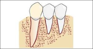
In cases where abutment teeth have weakened periodontal support due to periodontal disease or treatment-induced attachment loss, adjacent teeth may be splinted with crowns to help control the stresses applied to these teeth. By increasing the total area of the periodontal ligament, splinting two or more teeth enables stresses to be dispersed over a larger support. However, when a severely compromised tooth is splinted to another with significantly better periodontal support, the net effect may be a reduction in the support of the healthier tooth rather than an improvement in the weaker one.
Splinting with crowns also contributes to the stabilization of abutment teeth in the mesiodistal and anteroposterior directions. When one of the splinted teeth is a canine or when the splint extends anteriorly around the arch curvature, buccolingual stabilization is also achieved (Figure 1-31).
When two posterior teeth—such as molars or premolars—are splinted, their resistance to buccolingual stresses does not significantly increase.
Another indication for splinting arises when the abutment teeth exhibit tapering or short root morphology. Splinting two or more such teeth with crowns may simulate the effect of a multi-rooted abutment tooth, thereby enhancing support (Figure 1-32).
One of the cases where splinting is most necessary involves solitary abutment teeth that are bounded by edentulous spaces on both the mesial and distal sides. This situation is most commonly encountered in the second premolar region.
In certain cases, splinting can also be achieved through the clasps of an RPD (Figure 1-33); however, splinting with RPD is generally not preferred when fixed splinting is feasible.
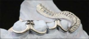
Splinting involves the use of clasps and occlusal rests on multiple teeth on both sides of the arch, along with the preparation of guide planes on several teeth. Not all clasps used in this context need to function as retentive arms; some buccal clasp arms may extend above the height of contour without providing retention, instead contributing to stabilization—and thus splinting. Studies have shown that when periodontally compromised teeth are rigidly supported, their mobility either decreases or remains unchanged. The most significant advantage of splinting with a removable partial denture is cross-arch stabilization. A lingual plate supports the teeth on either side of the arch, providing structural support and protection from horizontal stresses.
Preparation of guide planes
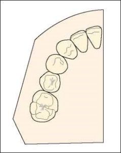
During the planning of a removable partial denture, friction control is achieved by preparing guide planes on as many teeth as possible. Guide planes are areas prepared on the proximal surfaces of the teeth, parallel to each other and to the path of insertion of the prosthesis (Video 1-34).
a) Convex proximal surfaces before preparation.
b) Guide planes shaped to the appropriate form.
These guide planes can be created on the enamel surfaces of the teeth or on any restorations. The frictional contact of the prosthesis with these parallel surfaces plays a significant role in enhancing its retention.
Rests designed to accommodate functional movement
The location of the occlusal rest must be taken into consideration when examining the torque and tipping forces that the clasp transmits to the abutment tooth as a result of the denture base’s movement.
The occlusal rest becomes the fulcrum point when an occlusal load is applied to a distal extension denture base. Thus, the type, direction, and strength of the forces applied to the abutment tooth depend on whether the occlusal rest is positioned on the mesial or distal surface.
When a distal occlusal rest is placed on the abutment tooth, one-third of the clasp’s retentive arm fits into the mesio-buccal undercut, and the reciprocal arm is positioned above the height of contour on the lingual surface. However, when a load is applied to a disal extension denture base, the mucosa is slightly compressed, causing the base to move in the tissue direction. Since the fulcrum is the occlusal rest, the components of the prosthesis distal to the rest will move into the tissue direction, while those mesial to the rest will move occlusally. In the planning of a distal occlusal rest, the first-class lever principle applies (Figure 1-35a).
As the retentive clasp is located in a mesial undercut of the occlusal rest, it moves upward, creating a distolingual force on the abutment tooth (Figure 1-35b).
Authors who advocate the use of a distal occlusal rest combined with a mesiobuccal undercut approach justify this treatment plan as follows: The use of a rigid reciprocal arm in conjunction with a flexible retentive arm allows for the neutralization of any forces generated by the retentive arm. Furthermore, the flexibility of the terminal one-third of the retentive arm reduces the magnitude of forces transmitted to the abutment tooth, ensuring that they remain within the physiological tolerance limits of the supporting structures.
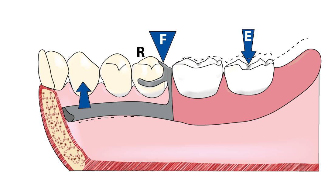
Another recommended approach involves a clasp design consisting of a mesial occlusal rest, a horizontal reciprocal arm, and a retentive arm placed in a distobuccal undercut. Positioning the occlusal rest mesially rather than distally, and locating the retentive arm within the distobuccal undercut, alters the direction of the stresses transmitted from the retentive arm to the abutment tooth. In a clasp design incorporating a mesial occlusal rest, the biomechanics follow the principles of a second-class lever. (Video 1-36).
Effect of second-class lever mechanics: The occlusal rest acts as the fulcrum (F) at one end of the lever, the distal extension base is subjected to occlusal force (E) at the opposite end,and the retentive tip of the clasp serves as the resistance (R) positioned between them.
When a mesial occlusal rest and a reverse Akers clasp, approaching the distobuccal undercut from the mesio-occlusal surface are used in distal extension dentures, as the denture base moves toward the tissue, the clasp tip moves into a deeper undercut area, and no torque is generated on the abutment tooth.
When occlusal load is applied to the denture base, the tip of the retentive arm moves gingivally, entering a deeper undercut and thus moving away from the tooth surface. This prevents the generation of torque on the abutment tooth. The advantage of this design lies in the extension of the lever arm, which represents the distance between the rest and the denture base. This increase in length causes the rotational movement of the denture base to become more upright in the ridge area during function. Vertical forces are better tolerated compared to horizontal oblique forces.
Although the mesial occlusal rest and distobuccal undercut approach have some planning advantages, the rigid horizontal reciprocal arm involved in this design generates stress in the mesiolateral direction on the abutment tooth. It should be noted that the reciprocal arm is positioned on the survey line and moves gingivally when occlusal load is applied to the base. Therefore, unlike the retentive arm that moves away from the abutment tooth, the rigid reciprocal arm generates stress on the buccal side of the abutment tooth when it is forced downward on the survey line.