Determining the direct retainers
The retention of a removable partial denture is directly influenced by the position, number, and type of the direct retainer on the arch. The simplest clasp suitable for providing adequate retention should be used. The clasp should offer good stabilization, remain passive until activated by functional stresses, and possess sufficient flexibility to allow limited movement of the denture base without transmitting torque to the abutment tooth.
Position and number of direct retainer
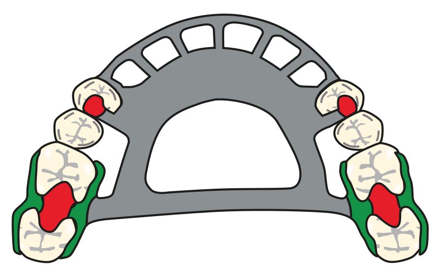
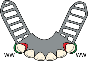
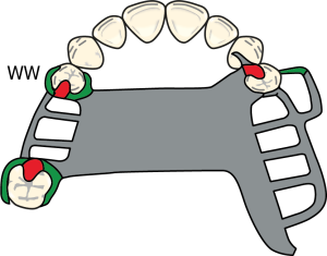
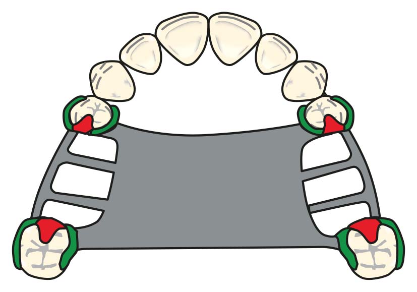
When determining the number and location of direct retainers to be used in a removable partial denture, the retention system and the fulcrum axis must be considered. Direct retainers are primarily placed starting from the posterior region of the arch, and the use of retainers in the anterior region should be avoided whenever possible (Figure 8-9).
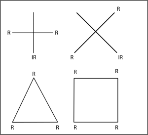
The ideal approach is to place three retainers in a triangular configuration, spaced as far apart as possible. The third retainer prevents rotation between the other two and enhances the overall stability of the retention system. If the existing undercuts on the abutment teeth are shallow or fewer in number, or if the guide planes are short and limited, additional direct retainers may be required. However, placing more than two retainers on the same plane does not provide a mechanical advantage and may lead to plaque accumulation and increased stress on the abutment teeth. In cases where only two abutment teeth are available, such as in distal extension removable partial dentures, only two direct retainers can be used. Clasp assemblies are not placed on secondary abutment teeth bordering anterior modification spaces due to esthetic concerns.
In Kennedy Class I cases, restoring short anterior modification spaces with fixed partial denture may also be considered as a treatment planning option. The same consideration applies to Kennedy Class II and Class III cases.
This approach should be evaluated when any of the following conditions are present:
- The abutment teeth surrounding the modification space provide adequate support according to the Ante’s law,
- The clinical crown heights of these abutments are suitable for fixed restorations,
- The abutment teeth present esthetic concerns due to substance loss, existing restorations, malformation, discoloration, or malposition,
- The abutments have undergone endodontic treatment and require reinforcement with a fixed restoration,
- When the patient has high esthetic expectations.
Short edentulous spaces in the premolar region that do not give additional support or retention in the treatment plan may also be restored with a fixed partial denture, provided that the above-mentioned criteria are met.
In cases where the edentulous spaces are short and the undercuts and guide planes are favorable, two direct retainers placed diagonally may provide sufficient retention. In such situations, occlusal rests placed on teeth without clasps function as indirect retainers, enhancing prosthesis stabilization and supporting the direct retainers.
Except in cases where the edentulous spaces are very short and the guide planes are particularly long, the use of a single direct retainer does not provide adequate retention. In these situations, additional support for retention is provided by maximizing tissue coverage, such as through the use of a full palatal plate.
When determining the location of clasp assemblies, their ability to effectively control stress must be taken into consideration.
Type of direct retainer
After deciding on the position and number of the retainers, the type of direct retainer to be used is selected.
The criteria influencing the selection of the direct retainer include:
- Condition of the abutment tooth,
- Amount of required flexibility,
- Effective use of survey line,
- Localization of retentive areas,
- Undercut depth and extent,
- Presence of soft tissue contour,
- Esthetics.
Condition of the abutment tooth: If the periodontal support of an abutment tooth is adversely affected by bone loss, placing a retainer on such a tooth should be avoided. If unavoidable, a more flexible retainer (such as a wrought wire clasp) should be selected to limit the load.
Amount of required flexibility: The required amount of flexibility determines the shape and material of the retainer. Clasps with longer or thinner arms provide greater flexibility. Using wrought wire clasps instead of cast clasps allows for a more flexible clasp design.
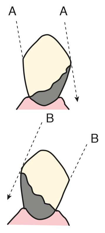
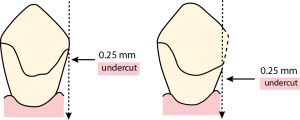
Effective use of survey line: The survey line is important because the rigid, non-flexible parts of the prosthesis should be planned above this line. Within the undercut area below the survey line, only the flexible parts of the prosthesis are designed. The only flexible component of a removable partial denture is the retentive tip of the clasp. When necessary, the path of insertion of the prosthesis can be altered to change the size and location of undercuts (Figure 8-10), or crown restoration of the abutment tooth may be considered to achieve adequate undercuts. Creating an undercut on the enamel of the abutment tooth for clasp placement is also a viable method (See. Mouth Preparation; Ch 10).
Localization of retentive areas: The localization of the retentive areas (undercuts) is important in the selection of the clasp type. The type of direct retainer is chosen by first identifying the retentive areas on the cast and evaluating the forces of varying magnitude and direction that tend to dislodge the removable partial denture in the occlusal direction.
Undercut depth and extent: During cast survey, when the contour height of the abutment tooth is determined using a carbon marker, the survey line emerges. The survey line divides the tooth into the “undercut area” (below the line) and the “non-undercut area” (above the line).
Ney classified survey lines into three categories:
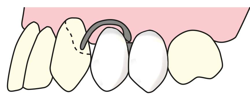
- The Class I survey line runs diagonally, with the undercut area located on the abutment tooth opposite to the edentulous space (Figure 8-11). Clasp options for the Class I survey line are shown in Figure 8-12.
- The Class II survey line also runs diagonally; however, the undercut area is located on the abutment tooth adjacent to the edentulous space (Figure 8-13). Different clasp options are considered for the Class II survey line (Figure 8-14).
- The Class III survey line runs horizontally, with undercut areas located on both sides of the abutment tooth; however, positioning close to the gingival margin is not preferred (Figure 8-15). Therefore, it can be converted into a Class I or Class II type survey line by recontouring. Clasp options for the Class III survey line are shown in Figure 8-16.
There are some recommendations regarding the localization of direct retainers:
- The retentive area being close to the edentulous space provides better retention.
- Retentive areas on natural teeth that are spaced apart should be utilized; this ensures balanced retention and stability in the removable partial denture.
- It is advantageous for the retentive areas to be located on the same surfaces of abutment teeth with equal depth on both sides of the dental arch.
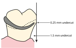
Undercut depth and extent: With the help of undercut gauges, the ideal placement of the retentive tip is ensured. This is because the clasp tip needs to flex an amount equal to the undercut depth when engaging or disengaging from the undercut area, highlighting the importance of accurate measurement.
In some cases, the preferred undercut depth may vary:
- Type of retainer: Bar clasps can be used with a deeper undercut compared to circumferential clasps.
- Material: Wrought wire clasps allow for a deeper undercut compared to cast clasps.
- Periodontal condition of the abutment tooth: A smaller amount of undercut should be used on a tooth with insufficient periodontal support.
Even if the amount of horizontal undercut is excessive, it is not necessary to use the largest undercut on the tooth surface. If the tip of the direct retainer is placed into a very wide horizontal undercut, it becomes impossible to insert or remove the prosthesis from the mouth.
If the removal of a prosthesis that was inserted under pressure is demanded:
- The retentive arm may deform due to forces exceeding its elastic limit.
- The retentive arm may fracture.
- The natural tooth or mucosa may be damaged.
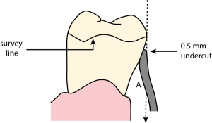
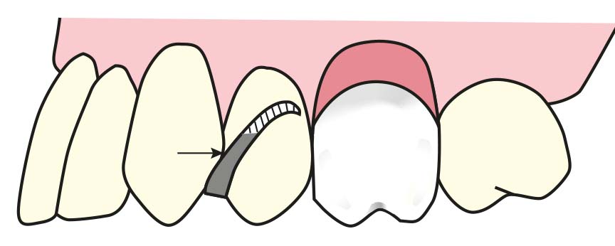
After determining the required amount of undercut, the area where the retentive tip will be placed is decided (Figure 8-17).
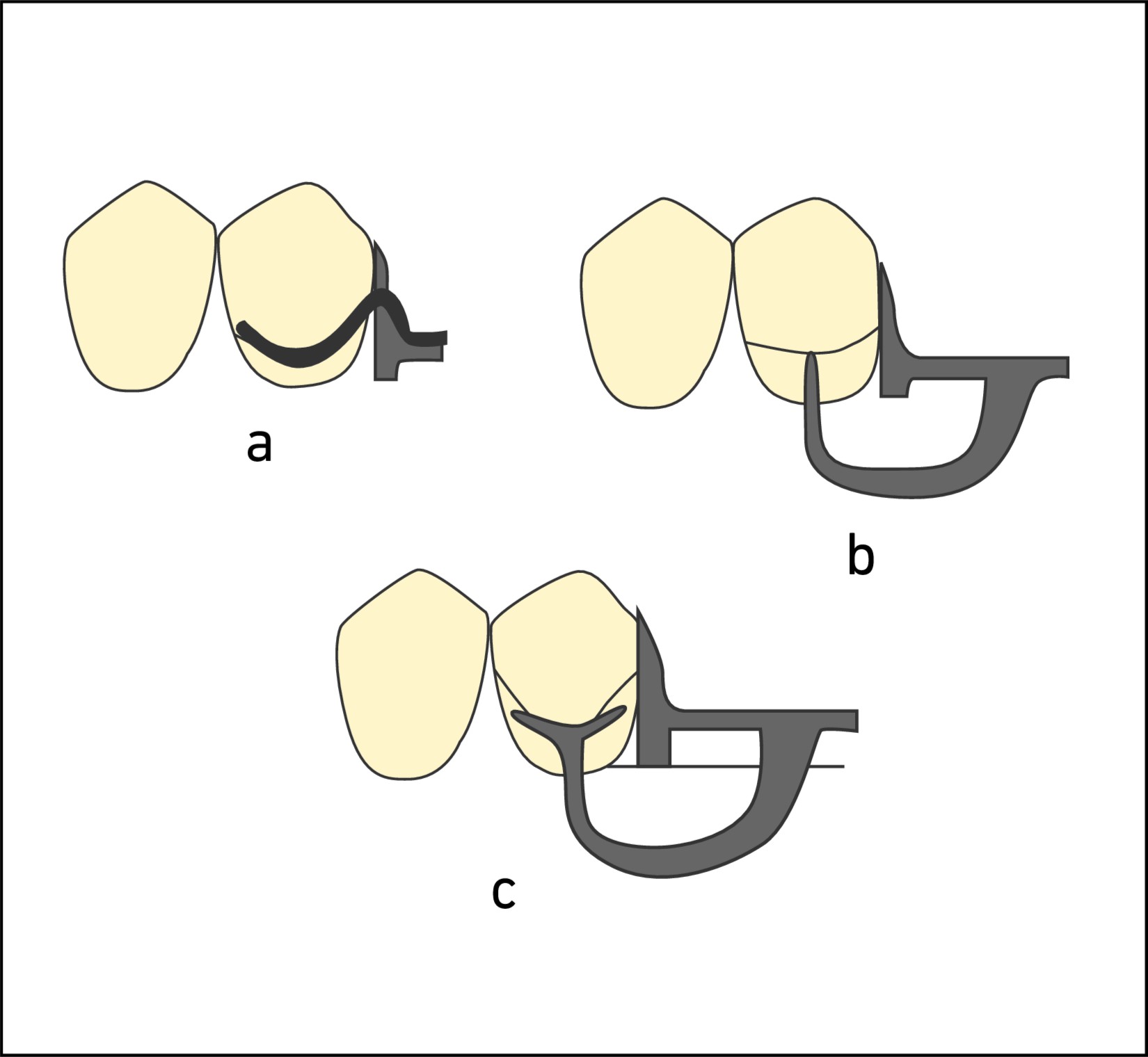
However, using a lighter degree of undercut on the tooth surface, with the retentive tip approaching the incisal or occlusal area, compromises aesthetics. Additionally, it can result in excessive relief space between the retentive clasp arm and the surrounding tissues (Figure 8-18). In this case, the tooth surface is modified to lower the level of the equator line (Figure 8-19).
If the tooth intended for clasping does not have a sufficiently wide undercut:
- The clasp is placed on another tooth.
- The number of clasps is increased.
- A clasping area is created by crown restoration.
When a more favorable undercut is present on the lingual surface of the abutment tooth, the clasp arm can be positioned on the lingual surface, while the reciprocal arm is placed on the buccal surface. Since the clasp arms remain passive on the tooth surface until activated, it is not necessary to position the clasp arm on the lingual surface of the opposing arch.
Presence of soft tissue contour: Undesirable tissue obstacles make the use of clasps approaching from the gingiva difficult. These include:
- Excessive tissue undercuts,
- Close frenulum attachments,
- Non-resorbed crests.
When the use of a bar clasp is required due to the presence of excessive tissue undercuts or close frenulum attachments, it should be aligned with the vertical slope of the minor connector and the acrylic base; however, a very thin space (approximately 1 mm) must be left between them. This allows flexibility for the function of the bar clasp while preventing food accumulation and tissue irritation (Figure 8-20).
In non-resorbed residual ridges, the minor connector of the bar clasp may be excessively bulky, compromising aesthetics. In such cases, an alternative type of direct retainer should be used. If this is not possible, the minor connector of the retainer is positioned to correspond with the interproximal space (Figure 8-21). In this case, to allow the clasp to flex, the minor connector must be left exposed; selective adjustment of the teeth arrangement is performed in this area.
Esthetics: During clasp planning, the amount of metal visible in the esthetic zone should be minimized:
- Clasps are placed on less visible teeth.
- Circumferential clasps are avoided in the anterior region.
- The clasp tip is kept as close as possible (about 1 mm) to the gingival margin.
- The use of distal rests is advantageous for bar clasps.
- Long guiding planes are preferred to reduce the number of clasps.
- Indirect retention is emphasized to enhance stability, allowing a reduction in the number of direct clasps.
- Circumferential (reverse Akers) clasps are avoided on the distal rests of premolar teeth because the bulky shoulder of the clasp would be highly visible (Figure 8-22).
Reciprocation
The retentive arms of the planned direct retainers should be balanced by a rigid stabilization arm or the denture base. In making this choice, the health of the tissues and the borders of the removable partial denture should be taken into consideration.
Cl I prostheses
Generally, only two direct retainers are used, typically one on each terminal abutment tooth. Unless the edentulous space is as short as a single missing tooth, the use of a cast circumferential clasp is not recommended.
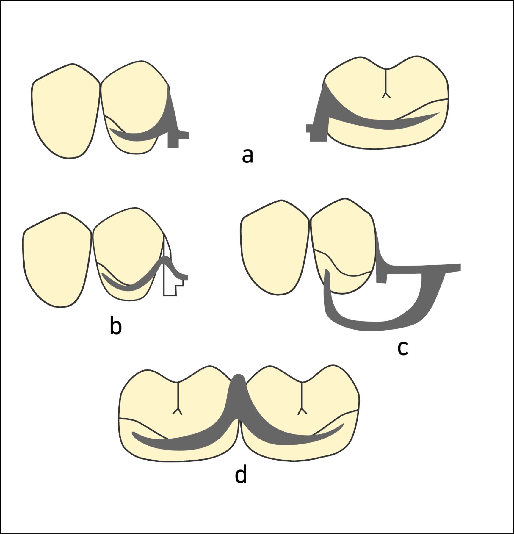
When a distobuccal undercut is present, the use of a bar clasp on premolar teeth is preferred (Figure 8-23). An alternative option is the reverse Akers clasp.
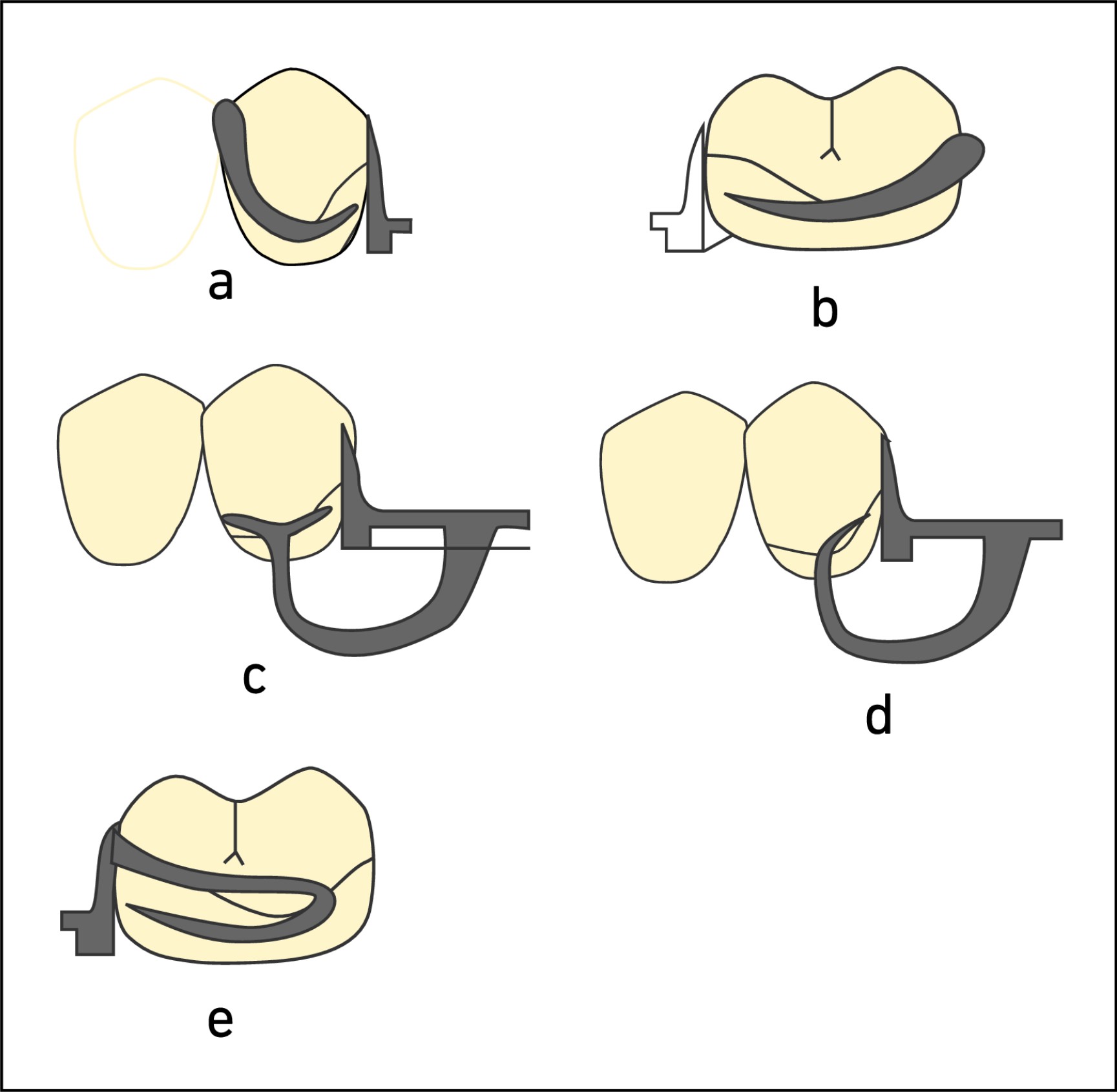
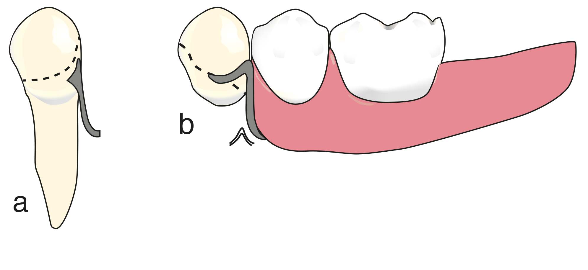
When a mesiobuccal undercut is present, a wrought wire clasp or gingival clasp is used (Figure 8-24). The approaching arm of the bar clasp is generally avoided, especially in the maxilla, due to potential esthetic concerns. However, in the mandible, the bar clasp may still be considered as an option.
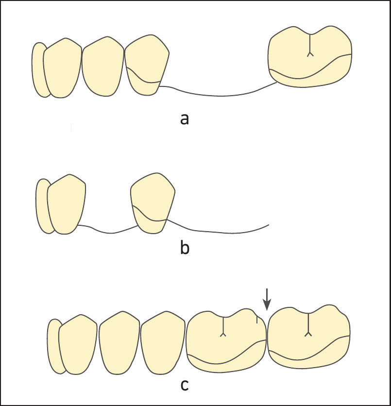
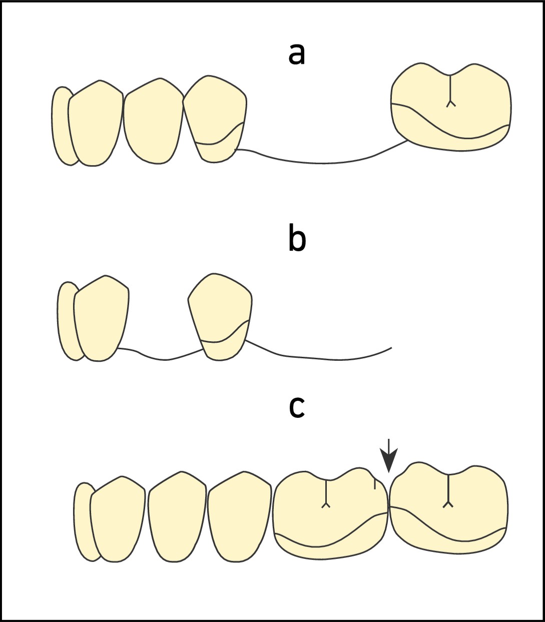
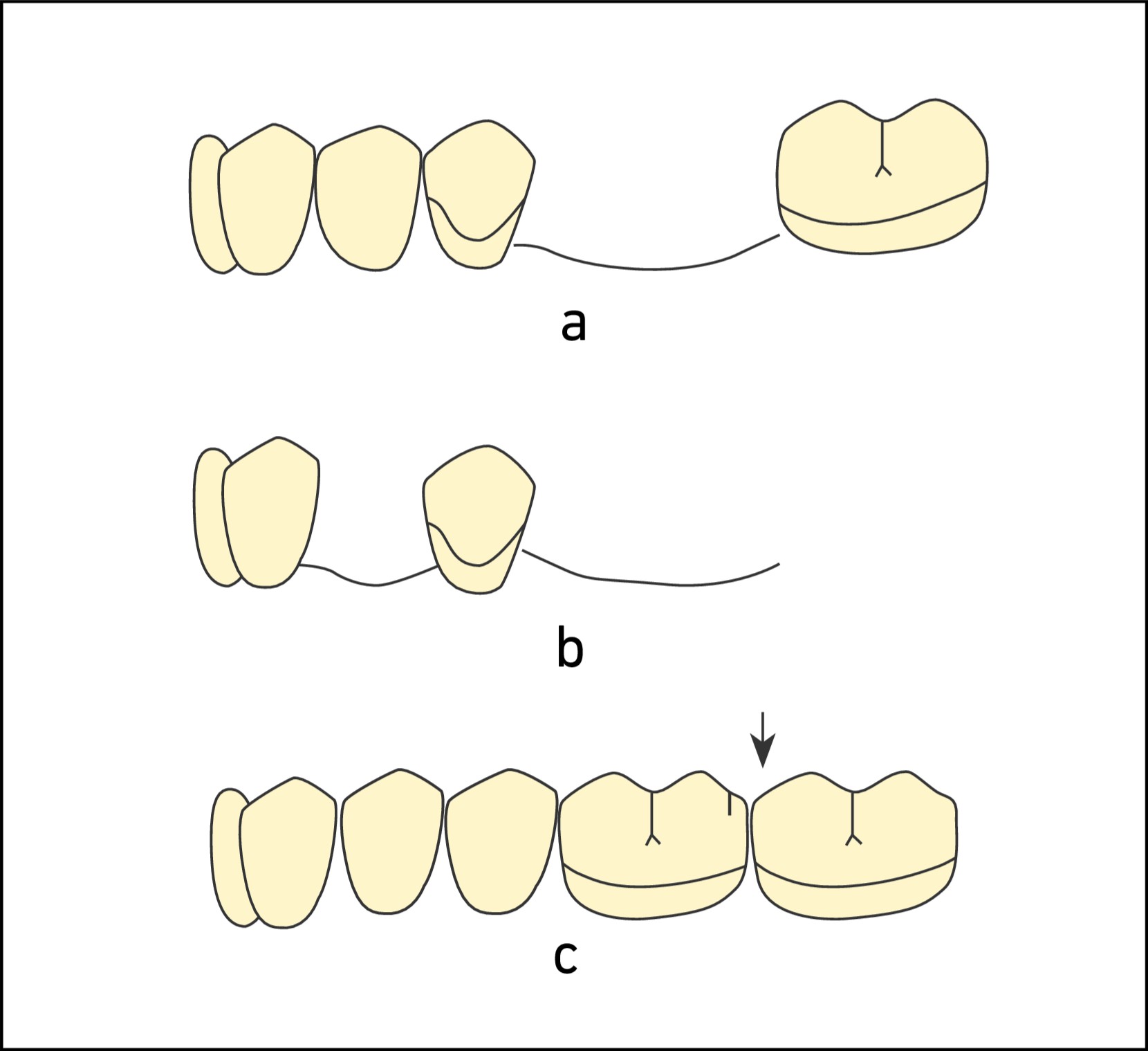
Due to esthetic concerns, the use of clasps is not recommended in anterior modification spaces (Figure 8-25 a-b).
- Resiprokal kroşe kolunun rijit olması gerekir. Kroşe sisteminin bu bileşeni gerektiğinde lingual plağa dönüştürülebilir.
Cl II prostheses
At least two clasps should be used and the clasp options considered for Cl I prostheses are valid for the free-end side. On the tooth-supported side, to provide stabilization of the opposing arch, a circumferential clasp is placed at the most posterior region of the arch whenever possible (Figure 8-26).
When a modification space is present on the tooth-supported side, the abutment teeth located anterior and posterior to the space are clasped. The clasp used on the abutment tooth anterior to the modification space is preferably flexible; because when the distal extension base rotates around the fulcrum axis, moving into the tissue, the clasp tip on the secondary abutment tooth anterior to the modification space is forced to move over the survey line. This causes it to be subjected to torque forces, similar to the abutment tooth located anterior to the distal extension denture base (Figure 8-27).
The other important factors need to be considered:
- The clasp type and the location of the retentive undercut are evaluated for suitability.
- Rigidity is essential in all reciprocal arms; a lingual plate can also be used instead of a reciprocal arm.
- Clasping is not used on abutment teeth surrounding anterior modification spaces (Figure 8-28).
Cl III prostheses
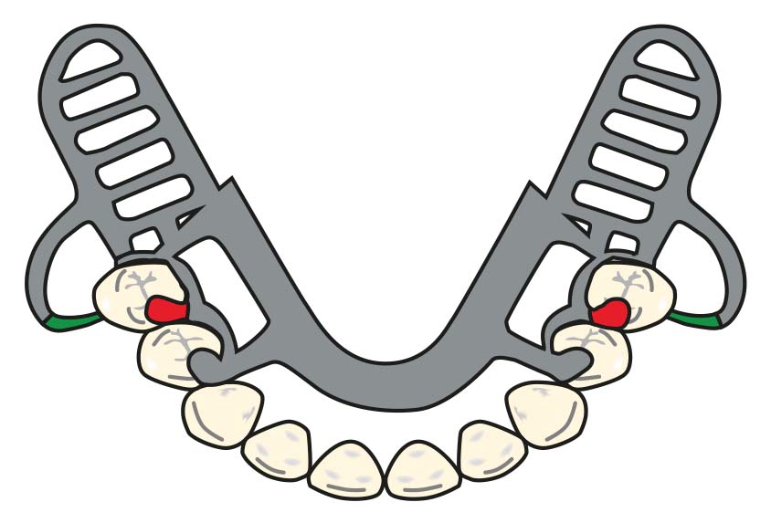
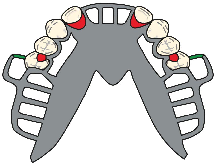
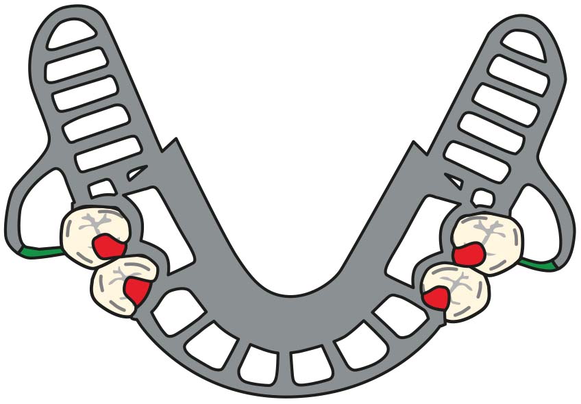
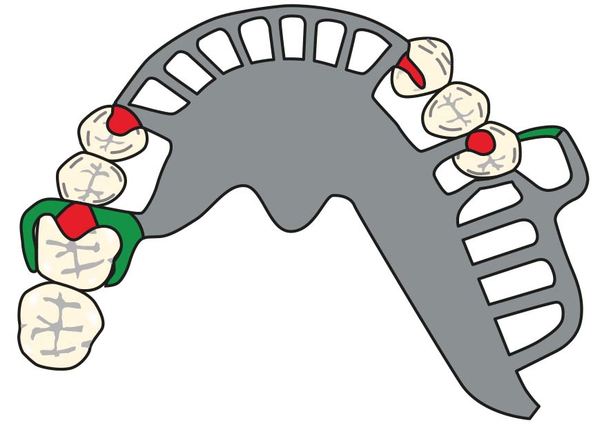
Three clasps are used: on the abutment teeth adjacent to the edentulous space and on the most posterior abutment tooth of the opposite arch, ensuring cross-arch stabilization (Figure 8-29a–b).
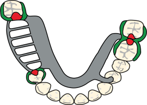
Figure 8-29 a. Cl III denture clasp designs for the maxilla.
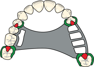
Figure 8-29 b. Cl III denture clasp designs for the maxilla.
In the presence of a modification space located opposite to the edentulous area, three or four clasps can be used depending on the periodontal condition of the abutment teeth (Figure 8-30).
In posterior abutment teeth, the Akers clasp is the simplest and most practical clasp type. For anterior abutments, bar or gingival clasps may also be preferred. If the periodontal health of the abutment teeth is adequate and the edentulous space is not long, need to increase the flexibility of the clasps is not essential.
Cl IV prostheses
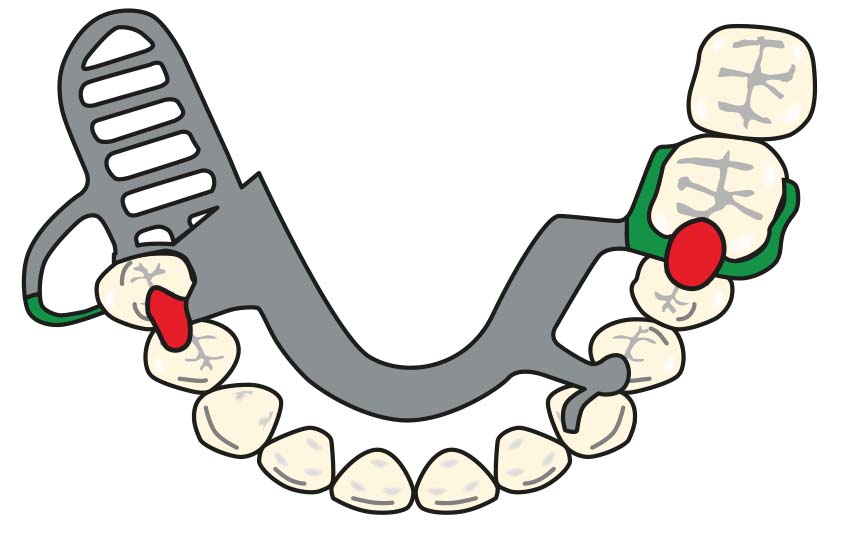
One or two Akers or double Akers clasps are used bilaterally on one or two most posterior abutment teeth in the arch. The choice of clasp type on anterior abutments may vary depending on the length of the edentulous area and the patient’s esthetic expectations (Figure 8-31). Guide planes are a more effective way to limit the movement of the anterior area of the prosthesis when clasps are not utilized on abutment teeth next to anterior edentulous spaces.