
Mandibular Kennedy Cl I
Mandibular Kennedy Cl I
Case 38. Figure 11.38
Case description and design parameters
Case classification:
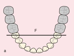
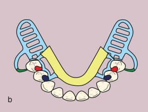
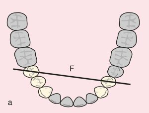
Two distal extension edentulous areas; Class I
Support areas:
Tooth support: Diametric fulcrum line passing between the terminal abutments of teeth 35 and 45
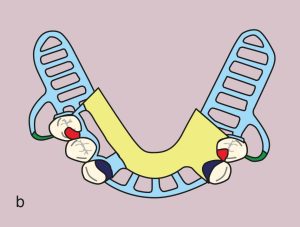
Occlusal rests: 35 and 45 (MO)
*In the presence of interocclusal interference: 35 and 45 (DO)
Tissue support: Mucosal support in the distal extension edentulous areas
Guide planes:
Distal extension: 35 and 45 (D)
Direct retainer:
Bar clasps: 35 and 45 (I bar; MB undercut, Modified T bar; DB undercut)
*In the presence of soft tissue undercuts: gingival clasp; 35 and 45 (MB undercut)
Reciprocation:
MO rests with proximal plates and stabilizing arms
Indirect retainer:
Auxiliary occlusal rests: 34 and 44 (MO)
*Effectiveness increases with the addition of canine extension to the auxiliary occlusal rest
Major connector:
Lingual bar
Minor connectors:
Elements connecting the approach arms of bar clasps, occlusal rests, indirect retainers, and artificial teeth to the major connector
Denture base and artificial teeth:
Distal extension bases; metal-acrylic base and acrylic artificial teeth
Case 39. Figure 11.39

Case 40. Şekil 11.40

Mandibular Kennedy Cl I modifications
Case 41. Figure 11.41
Case description and design parameters
Case classification:
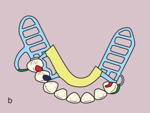
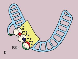
Two distal extension and one tooth-supported edentulous areas; Class I Mod 1
Support areas:
Tooth support: Diagonal fulcrum line passing between terminal abutments of teeth 34 and 45
Occlusal rests: 34 and 45 (MO), cingulum rests: 33 and 43
Secondary support: Cingulum rests; 33 and 43
Tissue support: Mucosal support in distal extension edentulous areas
Guide planes:
Distal extension: 34 and 45 (D)
Tooth-supported: 33 and 43 (M)
Direct retainer:
Bar clasps: 34 and 45 (I bar; MB undercut, Modified T bar; DB undercut)
Reciprocation: 34 and 33; proximal plate combined with lingual plate, 43, 44, and 45; proximal plate combined with stabilizing arm
Indirect retainer:
Cingulum rests; 33 and 43 combined with lingual plate
Major connector:
Lingual plate; marginal gingiva exposed in the area of 43, 44, and 45
Minor connectors:
Elements connecting the approach arms of bar clasps, cingulum rests, and artificial teeth to the major connector
Denture base and artificial teeth:
Distal extension bases; metal-acrylic base and acrylic artificial teeth