Maxillary Kennedy Cl II

Maxillary Kennedy Cl II

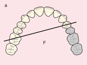
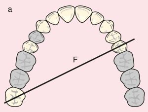
Case 16. Figure 11.16

Figure 11.16. a) Class II: Diagonal fulcrum line passing through the terminal abutments of teeth 25 and 17.
Figure 11.16. b) Metal framework design.

Case description and design parameters

Case classification:
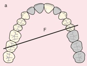
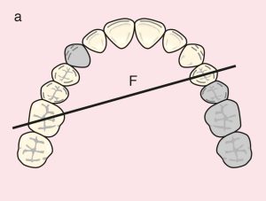
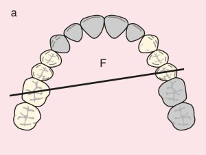
A single distal extension edentulous area; Class II

Support Areas:
Tooth support: Terminal abutments; a diagonal fulcrum line passing between teeth 25 and 17
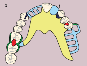
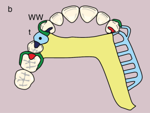
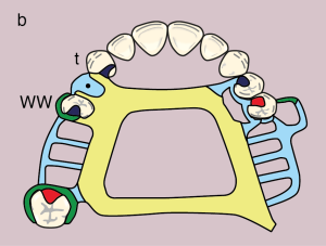
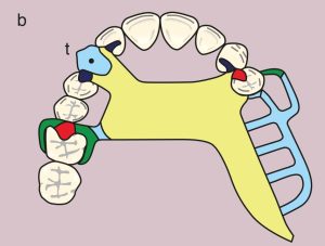
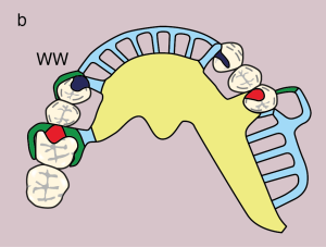
Occlusal rest: 25 (MO), embrasure rest: 16, 17
Tissue support: Mucosal support in the distal extension edentulous area

Guide Plane:
Distal extension; 25 (D)

Direct Retainer:
Bar clasp; 25 (I-bar on the MB undercut, modified T-bar on the DB undercut), and double Akers clasp; 16, 17
Reciprocation: 25, 16, 17; reciprocating clasp arm

Indirect Retainer:
Auxiliary occlusal rest; 14, 24 (MO)

Major Connector:
Palatal strap

Minor Connectors:
Elements that connect the approach arm of the bar clasp, the indirect retainer, the clasp, and the artificial teeth to the major connector

Denture Base and Artificial Teeth:
Distal extension base; metal-acrylic base with acrylic artificial teeth

Case 17. Figure 11.17

Figure 11.17. a) Class II: Diagonal fulcrum line passing through the terminal abutments of teeth 24 and 16.
Figure 11.17. b) Metal framework design.


Maxillary Kennedy Cl II modifications


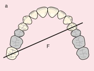
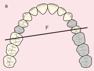
Case 18.
Figure 11.18

Figure 11.18. a) Class II Mod 1: Diagonal fulcrum line passing through the terminal abutments of teeth 23 and 16.
Metal framework design.
Figure 11.18. b) Metal framework design.

Case description and design parameters

Case classification:
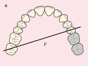
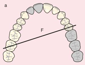
One distal extension and one tooth-supported edentulous area; Class II Mod 1

Support areas:
Tooth support: Terminal abutments; a diagonal fulcrum line passing between teeth 23 and 16
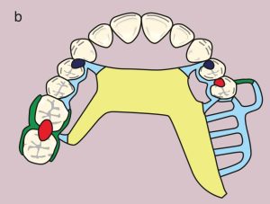
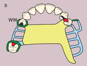
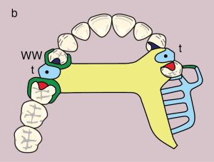
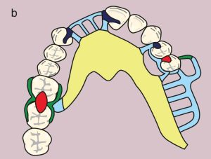
Occlusal rests: 15 and 16 (MO), cingulum rests: 13, 23
Secondary abutments: 13 and 15
Tissue support: Mucosal support in the distal extension edentulous area

Guide planes:
Distal extension: 23 (D); tooth-supported: 13 (D), 15 (M)

Direct retainer:
Gingival clasp; 23 (MB undercut) and Akers clasp; 16 (DB undercut), wrought wire clasp; 13 (MB undercut)
Reciprocation: 13 and 23 with rest and proximal plate; 16 with reciprocating clasp arm

Indirect retainer:
Cingulum rest: 13, occlusal rest: 15 (MO)

Major connector:
Palatal strap

Minor connectors:
Elements connecting the approach arm of the gingival clasp and the artificial teeth to the major connector

Denture base and artificial teeth:
Distal extension base: metal-acrylic base; modification area: metal base
Acrylic artificial teeth and tube tooth: 14

Case 19. Figure 11.19

Figure 11.19. a) Class II Mod 1: Diagonal fulcrum line passing through the terminal abutments of teeth 24 and 17.
Figure 11.19. b) Metal framework design
Figure 11.19. b) Metal framework desig

Case 20. Figure 11.20

Figure 11.20. a) Cl II Mod 2: Diagonal fulcrum line passing through the terminal abutments of teeth 25 and 18.
Figure 11.20. b)  Metal framework design.

Case 21. Figure 11.21

Figure 11.21. a) Cl II Mod 2: Diagonal fulcrum line passing through the terminal abutments of teeth 25 and 16.
Figure 11.21. b) Metal framework design.


Case 22. Figure 11.22

Figure 11.22. a) Cl II Mod 1: Diagonal fulcrum line passing through the terminal abutments of teeth 24 and 16.
Figure 11.22. b) Metal framework design.


Case 23. Figure 11.23

Figure 11.23. a) Cl II Mod 1: Diagonal fulcrum line passing through the terminal abutments of teeth 25 and 17.
Figure 11.23. b) Metal framework design.


Case 24. Figure 11.24

Figure 11.24. a) Cl II Mod 1: Diagonal fulcrum line passing through the terminal abutments of teeth 25 and 16.
Figure 11.24. b) Metal framework design.


Case 25. Figure 11.25

Figure 11.25. a) Cl II Mod 2: Diagonal fulcrum line passing through the terminal abutments of teeth 25 and 17.
Figure 11.25. b) Metal framework design.

License

A Guide to Removable Partial Denture Planning Copyright © 2025 by Funda Akaltan. All Rights Reserved.

Share This Book