Mandibular Kennedy Cl IV

Mandibular Kennedy Cl IV

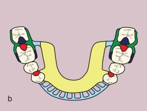
Case 52. Figure 11.52 

Figure 11.52. a) Cl IV: Diametric fulcrum axis passing through terminal abutments numbered 34 and 44.
Figure 11.52. b) Metal framework design

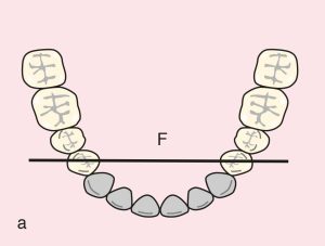
Case description and design parameters

Case classification:
One anterior edentulous space; Cl IV

Support areas:

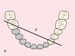
  • Tooth support: Terminal abutments; diametric fulcrum axis between teeth 34 and 44

  • Occlusal rest: 34 and 44 (DO)

  • Embrasure rest: 36, 37 and 46, 47

  • Tissue support: Mucosal support in the anterior edentulous area

Guide plane:
Free-end; 34 and 44 (M)
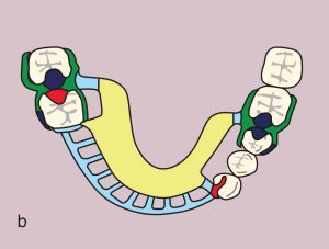
Direct retainer:
Double Akers; 36 (MB undercut), 37 (DB undercut), 46 (MB undercut), 47 (DB undercut)
Reciprocation: Reciprocal clasp arm

Indirect retainer:
Occlusal rest; 37 and 47 (MO)
Akers clasp; 36 and 46 (MB undercut)

Major connector:
Lingual plate

Minor connectors:
Those connecting Akers clasps and artificial teeth to the major connector

Prosthesis base and artificial teeth:
Anterior base; metal-acrylic base and acrylic artificial teeth

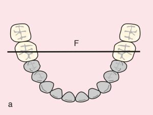
Case 53. Figure 11.53 

Figure 11.53. a) Cl IV: Diametric fulcrum axis passing through terminal abutments 36 and 46.
Figure 11.53. b) Metal framework design.


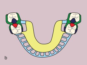
Case 54. Figure 11.54  

Figure 11.54. a) Cl IV: Diagonal fulcrum axis passing through terminal abutments 33 and 46.
Figure 11.54. b) Metal framework design

.

License

A Guide to Removable Partial Denture Planning Copyright © 2025 by Funda Akaltan. All Rights Reserved.

Share This Book