Minor connectors
Minor connectors serve as the denture components that connecting link between the major connector and the other components of the prosthesis, such as the retentive clasps, indirect retainers, and the denture base. In addition, they help distribute functional forces among the components of the prosthesis, thereby preventing the concentration of stress at a single area.
Minor connectors can be divided into four categories based on their location and purpose:
- Minor connectors that connect the circumferential clasp assemblies to the major connector,
- Minor connectors that connect the indirect retainers or auxiliary rests to the major connector,
- Minor connectors that connect the denture base to the major connector,
- Minor connectors that function as the approach arm of bar clasp assemblies.
Minor connectors that connect the circumferential clasp assemblies to the major connector
These minor connectors support the active components of the prosthesis, such as clasps and rests that prevent tissue-ward displacement. In order to provide adequate rigidity, they must possess sufficient bulk; however, their form should not interfere with tongue function. These connectors are typically located on the proximal surfaces of abutment teeth adjacent to edentulous ridges. In this position, the minor connector should be broad in the buccolingual direction but narrow mesiodistally. The thickest part lies on the lingual aspect of the proximal surface and tapers as it extends buccally. This shape facilitates the placement of artificial teeth in their natural alignment (Figure 5-21).
When the clasp is not used on an abutment tooth adjacent to the edentulous ridge, the minor connector is positioned within the embrasure between two teeth. Utilizing this triangular space for the metal allows the minor connector to achieve adequate bulk without causing discomfort to the tongue. Under no circumstances should the minor connector be placed on the convex lingual surfaces of the teeth (Figure 5-22).
Minor connectors that connect the indirect retainers or auxiliary rests to the major connector
These minor connectors, which extend from auxiliary occlusal rests to the major connector, should join the major connector at a right angle. However, the internal junctions must be rounded and carefully shaped to avoid sharp angles (Figure 5-23).
To conceal its bulk, the minor connector should be positioned within the embrasures between adjacent teeth. Its thickest portion should be located on the lingual surface and should gradually taper toward the contact areas to prevent tongue irritation. A minimum distance of 5 mm must be maintained between two vertical minor connectors.
Minor connectors that connect the denture base to the major connector
Minor connectors that join the denture base to the major connector may take the form of:
-
A lattice framework,
-
A mesh framework,
-
A metal base with retentive elements such as beads, pins, or nail-head projections.
These types of minor connectors must provide rigid support for the denture base while allowing artificial teeth to be arranged in their natural positions.
In distal extension cases, such minor connectors should extend over the residual ridge to cover the tuberosity in the maxilla, and should cover two-thirds of the edentulous ridge in the mandible.
The minor connector supporting the acrylic resin denture base must have adequate bulk at the junction with the major connector to resist fracture. The acrylic resin base should merge smoothly with the major connector, ensuring no irritation to the tongue or ridge tissues.
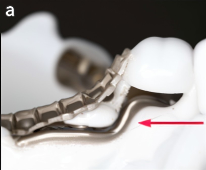
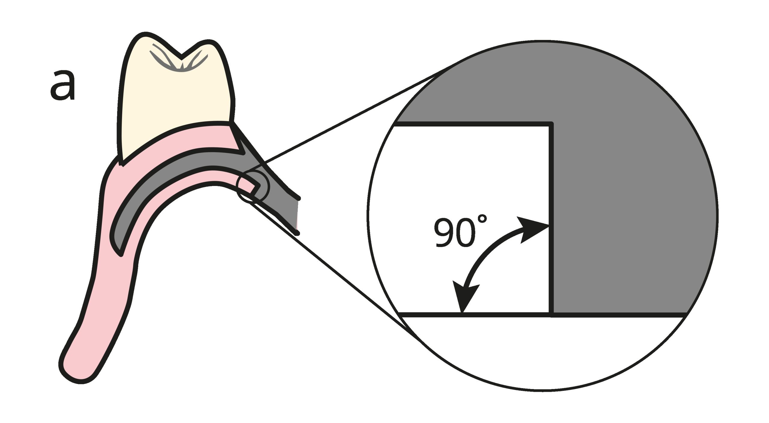
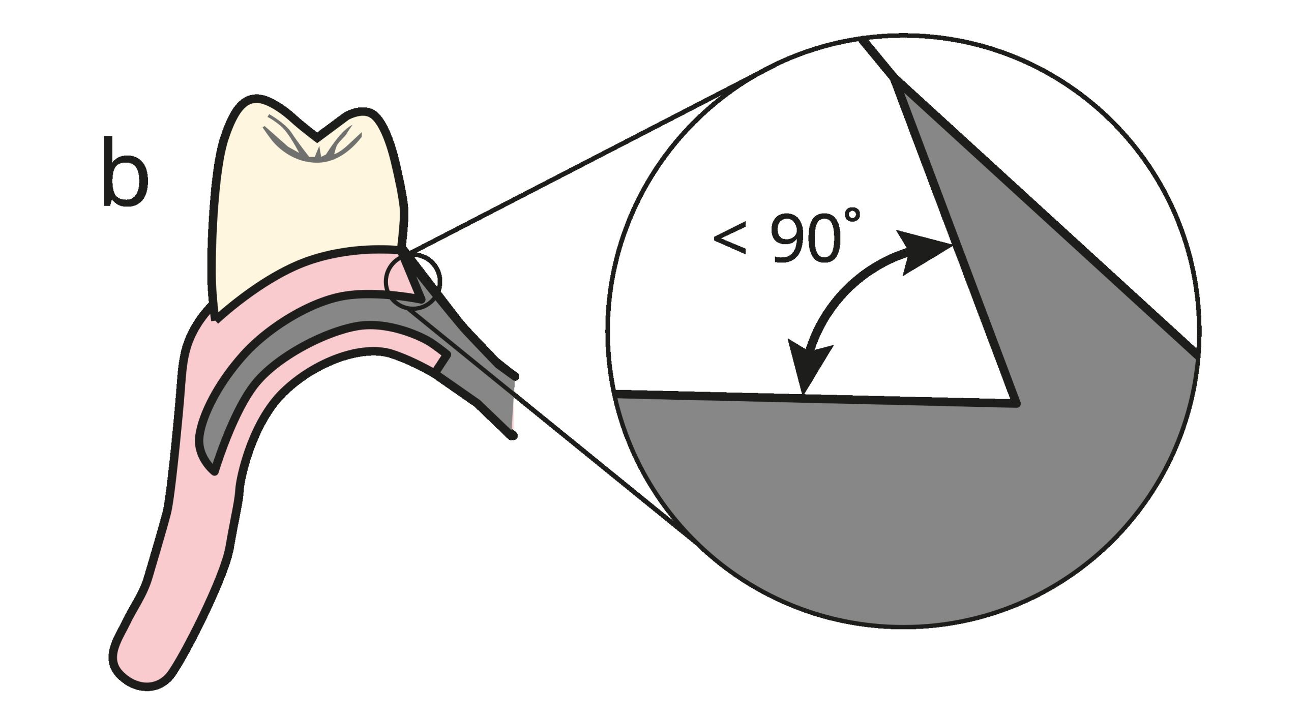
To avoid excessive thinning of the acrylic resin at its junction with the major connector, it is recommended that this junction form a 90° angle on the tissue surface of the prosthesis (Figure 5-24a). On the polished surface of the prosthesis, the junction angle is made less than 90° to enhance mechanical retention (Figure 5-24b).
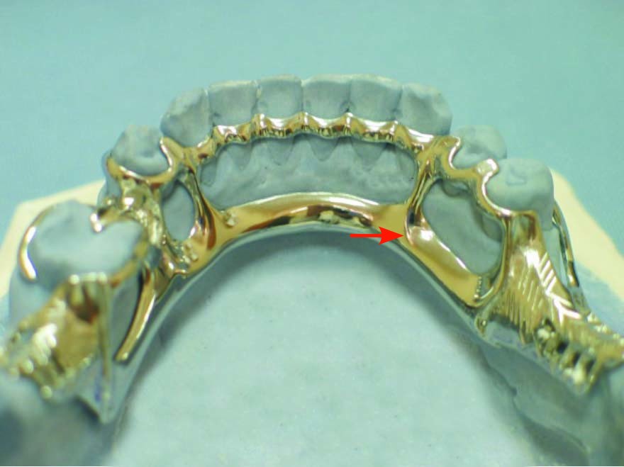
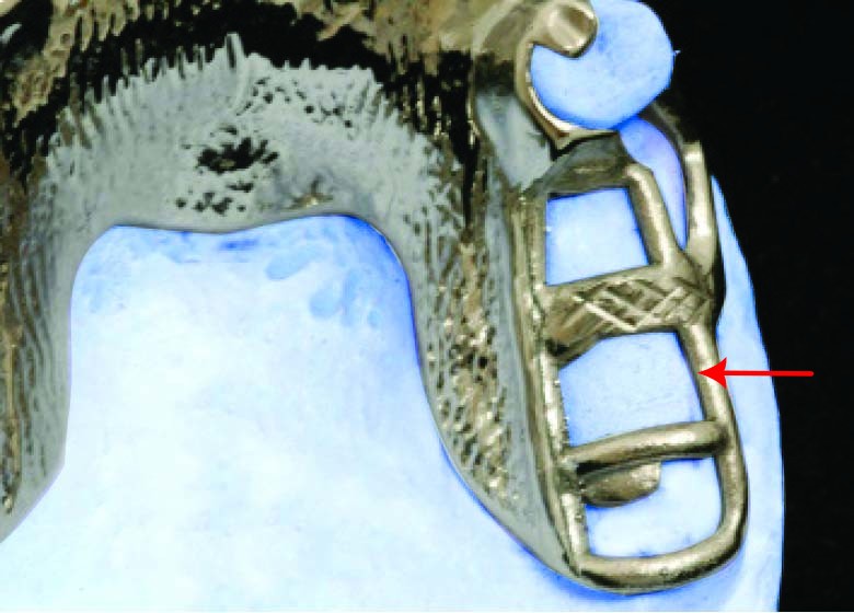
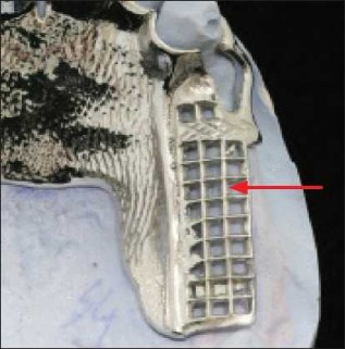
The part of the lattice framework extending parallel to the edentulous ridge is bordered by two metal struts. In the mandible, one strut is positioned on the buccal side of the ridge and the other on the lingual side. In the maxilla, a single metal strut is placed on the buccal side, while the ridge-facing border of the major connector serves as the lingual boundary (Figure 5-25).
The bands extending parallel to the ridge are thicker, and thinner metal bands cross them transversely to form the lattice structure. The number of transverse bands crossing the ridge is not critical; however, as their number increases, shaping the denture base and arranging the artificial teeth becomes more difficult. Typically, the number is determined so that one band is placed between each pair of artificial teeth.
Lattice framework is used in cases of extensive tooth loss. They provide a strong connection between the acrylic denture base and the underlying framework. When base relining is needed due to ridge resorption, the most effective retention is achieved with the lattice structure.
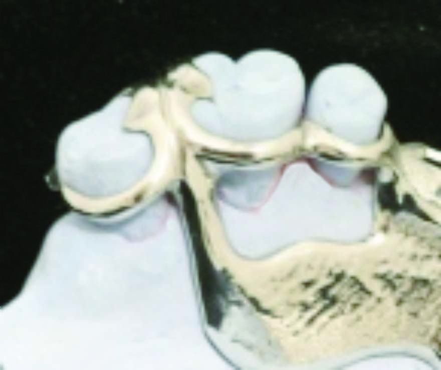
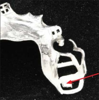
Mesh framework is similar to the metal bands of the lattice type in terms of their buccal, lingual, and posterior boundaries on the ridge. They resemble a metal plate with numerous small holes extending over the residual ridge and are used in cases of extensive tooth loss. However, during the acrylic processing stage, greater pressure is needed to allow the acrylic paste to fill the small holes, and the retention between the acrylic resin and the skeletal framework is not as strong as with the lattice type. This is because as the openings (holes) in the minor connector structure become smaller, retention decreases (Figure 5-26).
In distal extension removable partial dentures with lattice or mesh-type minor connectors, 2 mm² positive protrusions are present on the tissue surface to stabilize the framework during acrylic resin processing. These protrusions function as tissue stops and are located at the posterior end of the minor connectors, aligned with the center of the ridge (Figure 5-27).
If the terminal end of the minor connector is not supported by these protrusions, functional forces may cause displacement or deformation of the metal framework. In this region, the minor connector contacts the ridge through these positive stops, preventing the framework from being displaced into the ridge during acrylic processing.
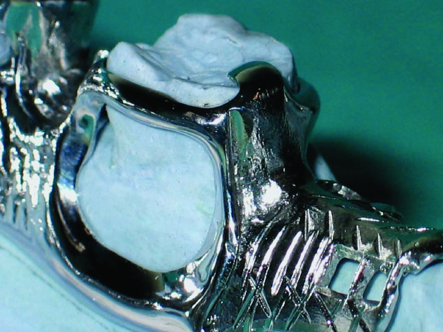
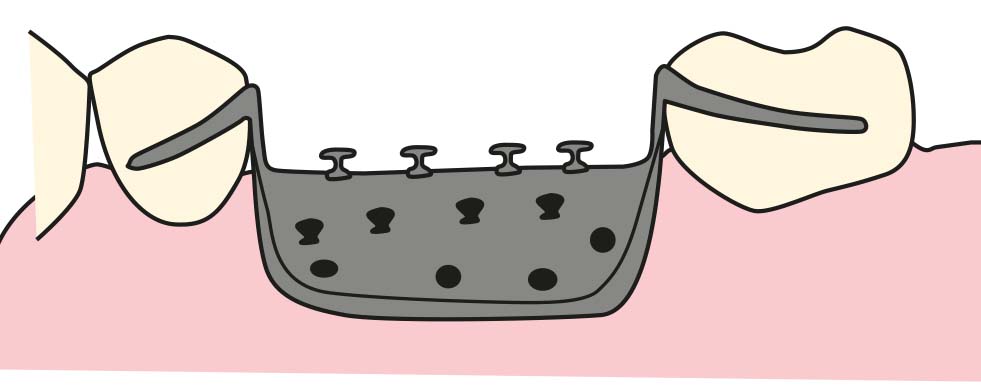
Bead, wire, or nailhead types are formed on the superior surface of the metal denture base, which directly contacts the mucosa over the edentulous ridge, and no relief is provided beneath the base. Retention of the acrylic resin denture base on the metal framework is achieved through these protrusions (Figure 5-28).
The denture base prepared in this way is more hygienic due to the use of metal, which provides a better tissue response compared to acrylic resin. However, there are some disadvantages as well. It is difficult to adapt the metal base, and when ridge resorption occurs, relining cannot be performed. Additionally, its retention with acrylic resin is weaker than that of other minor connector types. However, in cases where the distance between the upper and lower arches is limited and the acrylic resin alone cannot withstand occlusal forces, it functions successfully in tooth-supported dentures with minimal ridge changes.
Minor connectors that function as the approach arm of bar clasp assemblies
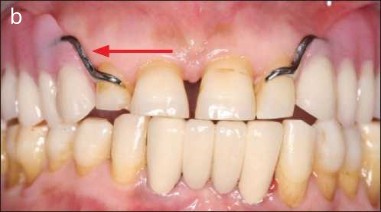
The approach arm is the only minor connector that does not need to be rigid. These minor connectors connect the retentive arm of the bar clasp to the major connector by approaching vertically from the gingival margin. From start to end, they display a progressively narrowing structure. Those connecting the gingival clasp to the major connector, on the other hand, extend horizontally (Figure 5-29 a-b). The approach arm of the gingival clasp is shorter than bar clasp’s approach arm; it must be shaped thinner to maintain flexibility and left outside the denture base border.