
Systematic approach to surveying a master cast
Once the master cast is mounted on the surveyor in the same orientation as the diagnostic cast, the parallelism of the guiding planes, as well as the location of survey lines and retentive areas, is evaluated using the analyzing rod.
The surveyor is used on the master cast for two main purposes:
- Drawing the survey line based on the height of contour and measuring the undercut
- Blocking out and relieving procedures
Measuring the undercut
By replacing the analyzing rod with a carbon marker, the survey line of each abutment tooth and the contours of the soft tissue are marked (Figure 7-16).
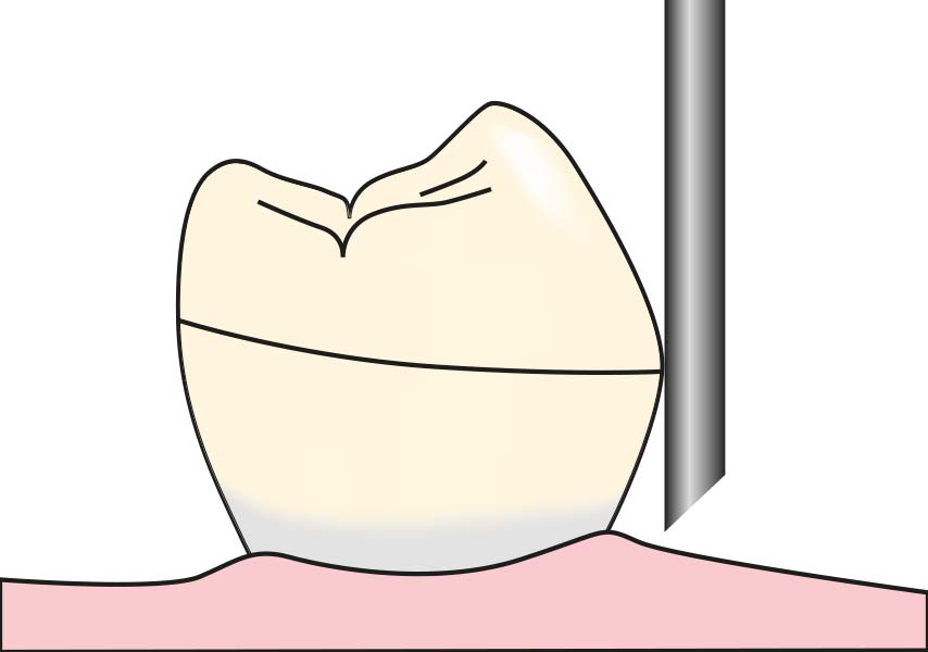
The carbon marker should be mounted parallel to the vertical arm of the surveyor and should contact the abutment tooth with its lateral surface. Carbon markers that have become worn and tapered through use are not recommended, as they tend to indicate a survey line located more occlusally than its actual position.
The amount of undercut can be measured using an undercut gauge attached to the surveyor. These gauges allow for measurements up to 0.03 inches (0.75 mm). Theoretically, although the ideal amount of undercut varies depending on clasp design, it is limited to 0.03 inches. In order to avoid torque on the abutment teeth, 0.01 inch (0.25 mm) of undercut is appropriate for cast circumferential clasps, 0.02 inch (0.5 mm) for bar clasps, and 0.03 inch (0.75 mm) for sufficiently long (at least 8 mm) wrought wire clasps. In cases requiring greater retention, such as when abutment teeth are located only on one side of the arch, it is preferable to clasp additional abutment teeth rather than increasing the amount of undercut.
An undercut gauge appropriate for the planned clasp design is mounted on the surveyor to identify the desired undercut area on the abutment teeth.
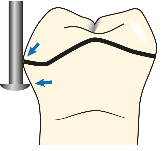
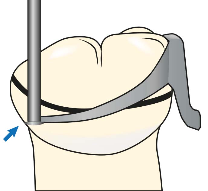
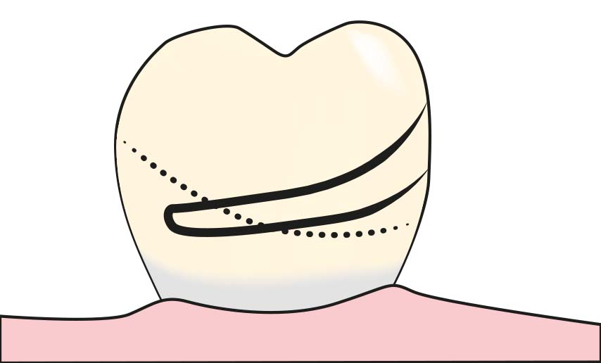
The undercut gauge should be positioned so that its tip touches the tooth surface while its lateral surface contacts the height of contour of the tooth (Figure 7-17). The point where the tip of the undercut gauge contacts the tooth surface is marked on the tooth by drawing (Figure 7-18). The final position of the clasp is drawn on the tooth surface with a permanent marker, ensuring that the tip of the clasp aligns with the point identified by the undercut gauge (Figure 7-19).
Blocking out and relieving procedures
Areas where the rigid components of the metal framework can prevent the prosthesis’s insertion and removal are noted by attaching a carbon tip to the model surveyor. Consequently, the areas that need to be blockout or relieved are determined.
After blocking out the areas where the rigid denture components will pass with the blockout material, these regions are trimmed using the surveyor blade parallel to the path of placement. Tissue undercuts to be filled are treated similarly to tooth undercuts.